Combined evaporator

An evaporator and combined technology, applied in the field of combined evaporators, can solve the problem that the falling film evaporator fails to solve the problem of "evaporating the working medium to dryness", and the falling film evaporation technology has not been widely promoted and applied, etc. problems, to achieve the effect of ensuring safety and overcoming more demands

Inactive Publication Date: 2011-08-31
GUANGZHOU INST OF ENERGY CONVERSION - CHINESE ACAD OF SCI
View PDF4 Cites 14 Cited by
  • Summary
  • Abstract
  • Description
  • Claims
  • Application Information

AI Technical Summary

Problems solved by technology

[0005] However, because the falling film evaporator fails to solve the problem of "evaporating to dryness" of the working fluid during the boiling evaporation process, the falling film evaporation technology has not been widely promoted and applied.

Method used


Image

  • Combined evaporator
  • Combined evaporator

Examples


Embodiment

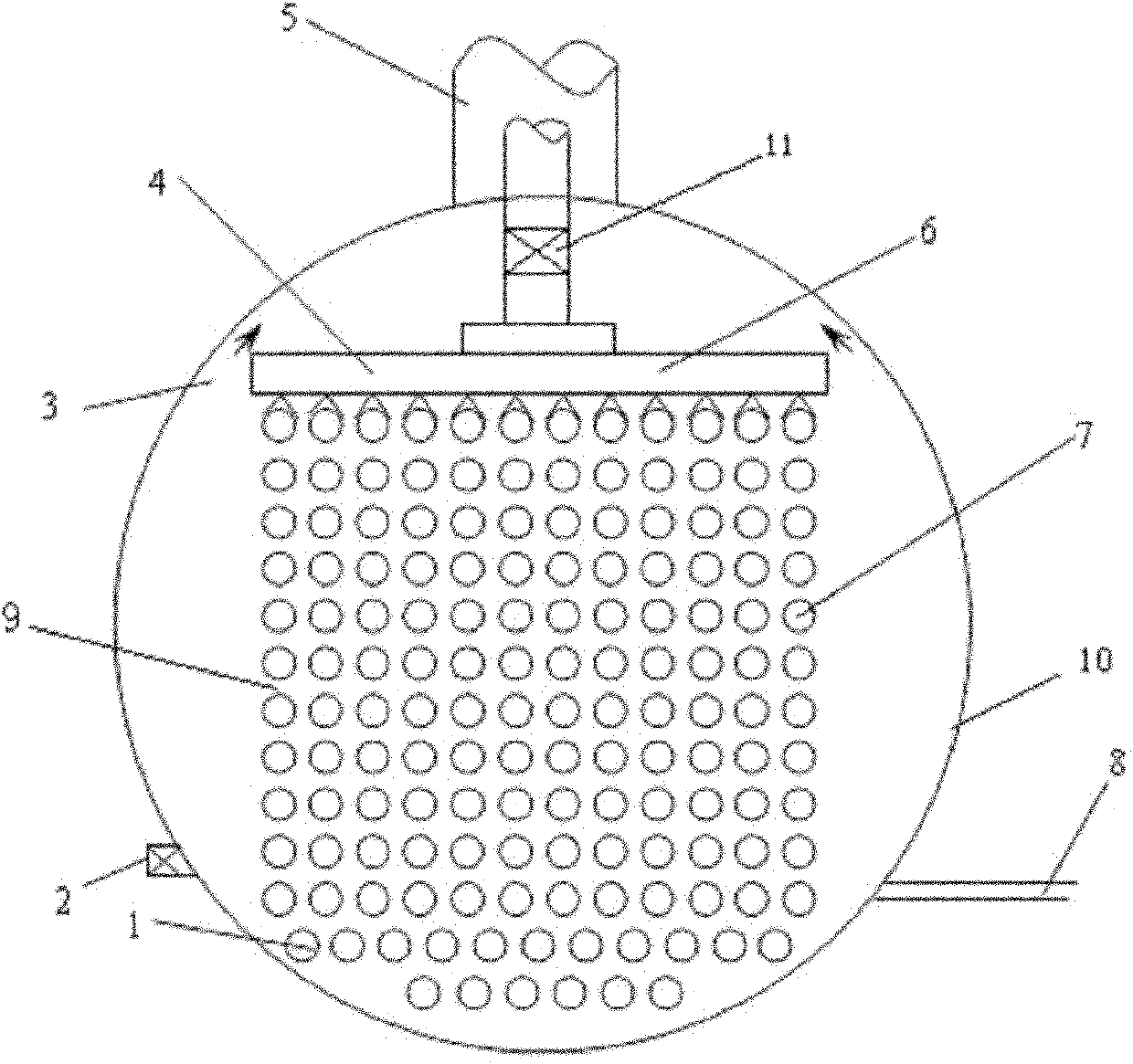
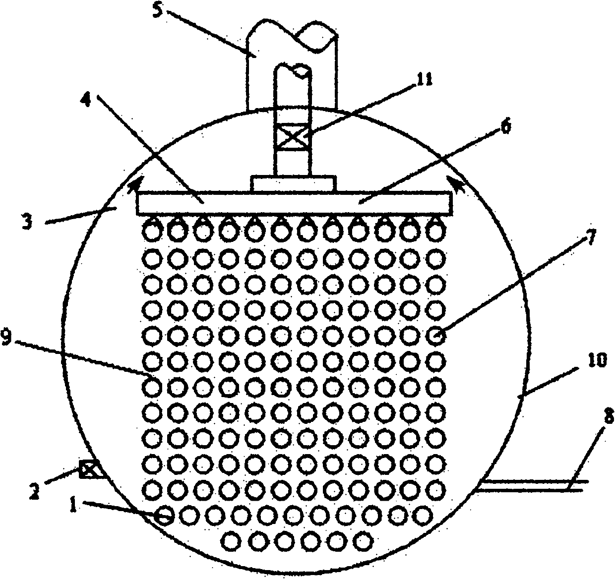
[0019] see figure 1 As shown, a combined evaporator includes an evaporator main body 10, a steam outlet 5 communicating with the evaporator main body 10, and a plurality of heat exchange outlets horizontally arranged in the evaporator main body 10 along the longitudinal direction of the evaporator main body 10. There are airflow channels 9 preset between adjacent heat exchange tubes; the heat exchange tubes include falling film evaporation heat exchange tubes 7 near the top of the evaporator body 10 and flooded heat exchange tubes near the bottom of the evaporator body 10 1. A film distribution device 4 is provided above the falling film evaporation heat exchange tube 7, and the film distribution device 4 has a low boiling point working fluid inlet 6. The width of the film distributor 4 is equal to the row width of the falling film evaporation heat exchange tubes 7 .

[0020] In the evaporator of the present invention, if the liquid level is too high, the heat transfer effici...


PUM


Abstract

The invention discloses a combined evaporator comprising an evaporator body and a steam outlet communicated with the evaporator, wherein a plurality of heat exchange tubes are horizontally arranged in the evaporator body along the longitudinal direction of the evaporator body; an airflow path is arranged between adjacent heat exchange tubes; the heat exchange tubes comprise a falling film type evaporation heat exchange tube and a flooded heat exchange tube, wherein the falling film type evaporation heat exchange tube is near the top of the evaporator body; the flooded heat exchange tube is near the bottom of the evaporator body; and a film distribution device is arranged above the falling film type evaporation heat exchange tube and is provided with an inlet for a low-boiling-point working medium. Compared with the prior art, the combined evaporator combines the advantages of two evaporators; the problem that the half heat exchange tubes at the lower half always have dry spots because uneven liquid distribution is solved, and the safety of the evaporator is guaranteed; the defect of large evaporated liquor demand in the flooded heat exchange tube is overcome; the evaporation area of the heat exchanger is fully utilized; and evaporation efficiency is still kept in a higher level.

Description

technical field [0001] The invention relates to a combined evaporator for endothermic evaporation of low-boiling-point working fluid in an organic Rankine cycle. Background technique [0002] The evaporator used in the low-temperature ORC is mainly a falling-film evaporator. The patent of the falling film evaporator was registered in 1888, but there were few related studies before 1970. The research from 1970 to 1990 mainly focused on the application of the ocean thermal energy conversion system (OTEC) until after 1990. The gradual ban of CFCs has only once again attracted people's attention. [0003] During the evaporation process of the falling film evaporator, the high-pressure liquid passing through the film distributor is sprayed into the evaporator by its own pressure and atomized, and the throttling and pressure reduction process is also completed. The throttling and atomized liquid is uniformly dispersed in the upper space of the evaporator, and under the double ac...

Claims


Application Information

Patent Timeline
Patent Type & Authority Applications(China)
IPC IPC(8): B01D1/22
Inventor 徐琼辉马伟斌龚宇烈王福敏
Owner GUANGZHOU INST OF ENERGY CONVERSION - CHINESE ACAD OF SCI
Why Eureka
Try Eureka