
High-strength turnout switch

A point switch, high-strength technology, applied in the direction of point switches, roads, tracks, etc., can solve problems such as insufficient strength, and achieve the effects of convenient laying, simple production process, and increased strength

Inactive Publication Date: 2011-08-24
王萍 +5
View PDF5 Cites 17 Cited by
  • Summary
  • Abstract
  • Description
  • Claims
  • Application Information

AI Technical Summary

Problems solved by technology

[0003] In order to overcome the shortcomings of insufficient strength of the existing switch switch, the present invention provides a high-strength switch switch

Method used


Image

  • High-strength turnout switch
  • High-strength turnout switch
  • High-strength turnout switch

Examples


Embodiment Construction

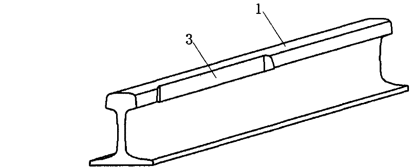
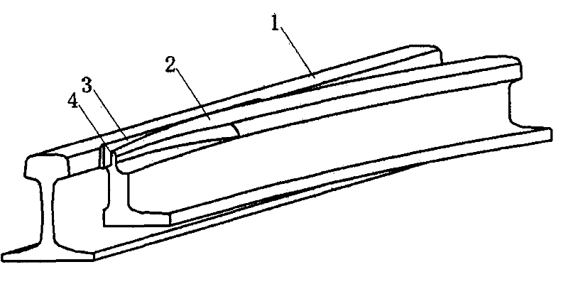
[0015] see Figure 1~4 The composition of this high-strength turnout switch includes a straight basic rail 1 and a curved point rail 2, and its characteristic is that the abutment surface 3 of the straight basic rail 1 and the curved point rail 2 is a concave vertical abutment The abutment surface of the curved point rail 2 and the straight basic rail 1 is a vertical fitting surface 5, and the rail head 4 of the curved point rail is a recessed fitting surface 3 that can be hidden in the straight basic rail. Flat rail head. Figure 5-7 The cross-sectional views of the curved point rail attached to the straight basic rail are given.


PUM


Abstract

The invention discloses a high-strength turnout switch, and belongs to the technical field of railway assembly manufacture. The turnout switch comprises a straight basic rail and a curved point rail. The turnout switch is characterized in that: the surface, attached to the curved point rail, of the straight basic rail is a sunken vertical abutted surface; the surface, attached to the straight basic rail, of the curved point rail is a vertical abutted surface; and the rail head of the curved point rail is a flat rail head capable of being concealed in the sunken abutted surface of the straight basic rail. The turnout switch has the advantages that: the point end of the original curved point rail is widened to improve the strength of the point end of the curved point rail; and correspondingly the abutted surface of the straight basic rail is changed into the vertical abutted surface capable of accommodating the widened point end of the curved point rail, so that the transition distance from the point end of the curved point rail to the width of the complete rail head is shortened at the same time of ensuring abutting, namely the length of the weak section of the curved point rail is reduced, the load bearing capacity and the abrasion resistance of the curved point rail are improved, and the service life of the curved point rail is greatly prolonged. The turnout switch is particularly suitable to be used in heavy-duty line turnouts.

Description

technical field [0001] The invention relates to a switch switch used on railway lines, belonging to the technical field of railway component manufacturing. Background technique [0002] At present, the abutment method of the curved point rail and the straight basic rail in the switch point of the railway switch usually adopts the hidden point abutment, that is, the tip of the curved point rail is hidden under the head of the straight basic rail, and the straight basic rail is at the hidden point of the curved point rail. There is an oblique cutting surface from the inside to the outside at the bottom of the rail head. This cutting surface does not reach the top surface of the rail head. There is a corresponding oblique cutting surface at the rail head of the curved point rail corresponding to the cutting surface and the straight basic rail. , the head of the curved point rail becomes a gradually changing shape from being hidden under the head of the straight basic rail to th...

Claims


Application Information

Patent Timeline
Patent Type & Authority Applications(China)
IPC IPC(8): E01B7/00E01B7/02
Inventor 王平陈嵘肖杰灵曹洋刘学毅魏贤奎
Owner 王萍
Learn More