


Quick Research
Generate reliable direction feasibility study reports for your R&D in just a few steps.

Technical Q&A
Discover and master advanced knowledge NOW. Basics, ideas, possibilities, all at once.

Find Solutions
As an expert in R&D theories, this can generate solutions to your technical problems instantly.

Evaluate Feasibility
Analyze your overall solution with one click, know your potential R&D risks in advance.

Monitor Landscape
Get weekly tech updates, stay abreast of the latest tech innovations and key insights.
Method for operating light emitting diode and circuit arrangement
A technology of light-emitting diodes and driving units, applied in the field of circuit devices, can solve the problems of persistent damage of light-emitting diodes, heating of light-emitting diodes, etc., and achieve the effect of avoiding damage and realizing voltage measurement.
- Summary
- Abstract
- Description
- Claims
- Application Information
AI Technical Summary
Problems solved by technology
Method used
Image

Examples
Embodiment Construction
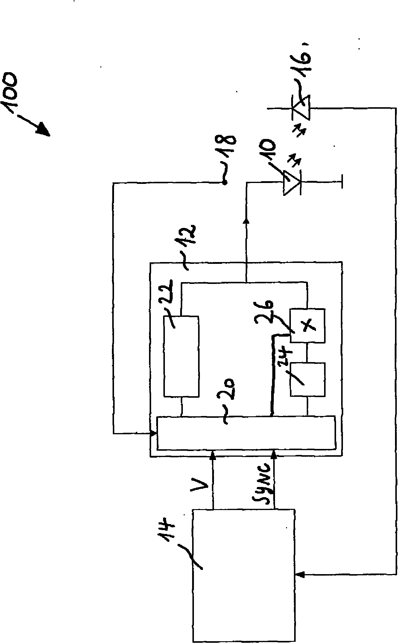
[0022] represented by 100 as a whole and in figure 1 The video projection device shown schematically in includes light-emitting diodes, where a light-emitting diode 10 is shown symbolically. The driver circuit 12 supplies these light-emitting diodes with a light-emitting diode current ILED. The current intensity ILED is determined according to a specification V which is established by a control unit 14 outside of the driver 12 and supplied to the driver 12 . This specification determines the current intensity of the individual light-emitting diodes 10 such that the light emitted by the light-emitting diodes has a predetermined color locus. That is, the chromaticity coordinates are determined by the current intensity ILED.
[0023] It is provided that V is determined in the range of regulation, ie the control unit 14 regulates according to a predetermined chromaticity coordinate or a predetermined intensity of the light emitted by the light-emitting diode 10 . Specifying V m...
PUM
 Abstract
Description
Claims
Application Information
 - R&D Engineer
- R&D Manager
- IP Professional
- Industry Leading Data Capabilities
- Powerful AI technology
- Patent DNA Extraction
Browse by: Latest US Patents, China's latest patents, Technical Efficacy Thesaurus, Application Domain, Technology Topic, Popular Technical Reports.
© 2024 PatSnap. All rights reserved.Legal|Privacy policy|Modern Slavery Act Transparency Statement|Sitemap|About US| Contact US: help@patsnap.com