
Very low voltage millimeter wave injection-locked dichotomous frequency divider

A two-frequency divider, injection locking technology, applied in the direction of electrical components, automatic power control, etc., can solve the problem of limited operating frequency range of the injection locking frequency divider, affecting the stable operation of the frequency divider, etc.

Inactive Publication Date: 2011-08-17
FUDAN UNIV
View PDF4 Cites 11 Cited by
  • Summary
  • Abstract
  • Description
  • Claims
  • Application Information

AI Technical Summary

Problems solved by technology

However, the disadvantage of the injection-locked frequency divider is that its operating frequency range is very limited, and the process deviation and temperature deviation in the actual chip manufacturing process will seriously affect the stable operation of the frequency divider

Method used


Image

  • Very low voltage millimeter wave injection-locked dichotomous frequency divider
  • Very low voltage millimeter wave injection-locked dichotomous frequency divider
  • Very low voltage millimeter wave injection-locked dichotomous frequency divider

Examples


Embodiment Construction

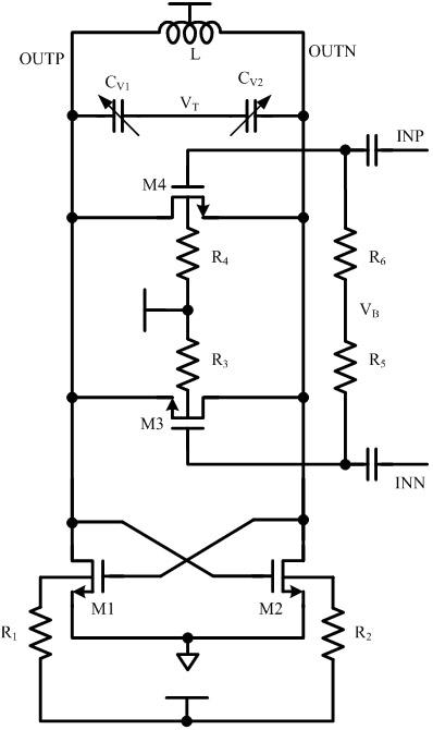
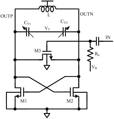
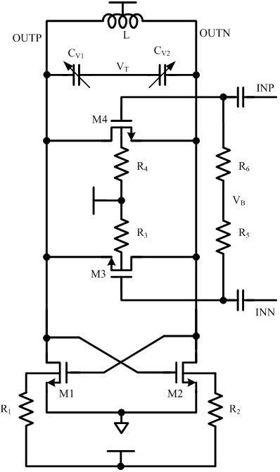
[0008] In practical applications, the injection-locked frequency divider is often used as a part of the clock generation circuit. The input signal is usually the output signal of the oscillator in the phase-locked loop. It has the highest operating frequency in the entire circuit and is also the stage with the largest power consumption. The typical application of the injection-locked frequency divider proposed by the present invention is as the first stage in the entire frequency divider chain, and its low voltage advantage can reduce the power consumption of the entire frequency divider chain, while the forward body bias Technology can expand its frequency locking range and ensure the stable operation of the post-stage frequency divider circuit. Compared with the traditional single-ended input method, the differential input method is convenient to be cascaded with the previous circuit, eliminating the need for matching circuits that are often required in previous circuits. Th...


PUM


Abstract

The invention belongs to the technical field of millimeter wave integrated circuits and specifically relates to an injection-locked dichotomous frequency divider applied in an integrated circuit of a transceiver. The injection-locked dichotomous frequency divider comprises an inductance and capacitance oscillator, a tuning circuit and a signal injection circuit, wherein the tuning circuit is tuned by a varactor, the inductance and capacitance oscillator performs self-excited oscillation at certain frequency without external input excitation, and the signal injection circuit is used for injecting an input signal into a resonant cavity of the oscillator for realizing traction and locking of the self-excited frequency of the oscillator, thereby realizing dichotomous frequency division of the input signal. Compared with a traditional injection-locked circuit, an additional matching circuit is eliminated, the power consumption and the area required for a chip are significantly reduced, the injection efficiency is improved, and the locking range of the frequency divider is expanded. By using the forward body bias technology, the circuit can realize wider working frequency under lower voltage of a power supply, and the circuit can realize differential input.

Description

technical field [0001] The invention belongs to the technical field of millimeter wave integrated circuits, and in particular relates to an injection locked frequency divider (Injection Locked Frequency Divider) applied to millimeter wave frequency band integrated circuits. The millimeter-wave transceiver system of the frequency divider realizes the two-frequency division function of the millimeter-wave frequency band signal. Background technique [0002] With the development of modern information technology, the requirements for high-speed wireless communication technology are becoming more and more intense, which prompts people to continuously develop higher frequency band resources and study millimeter wave communication technology. At the same time, with the continuous decline of process feature size, especially the development of ASICs, low power consumption design has become an inevitable requirement for circuit design in various communication systems. In this context...

Claims


Application Information

Patent Timeline
Patent Type & Authority Applications(China)
IPC IPC(8): H03L7/18
Inventor 任俊彦傅海鹏蔡德鋆陈丹凤李巍李宁叶凡
Owner FUDAN UNIV
Learn More