
Whole-course adjustable digital pulse width modulator based on oscillation ring circuit

A digital pulse width modulation and oscillation loop technology, applied in the field of electronics, can solve the problem that the duty cycle of the output pulse width signal cannot be adjusted in a full range, affect the adjustment speed and accuracy of the output voltage of the power supply, reduce the effective resolution of DPWM, etc. The effect of limited duty cycle size, guaranteed effective resolution, and optimized adjustment speed and accuracy

Active Publication Date: 2013-06-05
SOUTHEAST UNIV
View PDF3 Cites 0 Cited by
  • Summary
  • Abstract
  • Description
  • Claims
  • Application Information

AI Technical Summary

Problems solved by technology

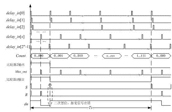
However, the DPWM with the oscillation ring structure uses the RS latch in the output logic circuit, and its set (S) terminal signal is obtained by several signal logics such as a counter and a comparator. The secondary setting error, and then the output pulse width signal is wrong when the duty ratio is small
Therefore, the output pulse width signal in this structure is affected by the number of counter bits m limit, cannot correctly generate lower than (1 / 2 m )×100% duty cycle signal, which reduces the effective resolution of DPWM, thereby affecting the adjustment speed and accuracy of the output voltage of the power supply
[0005] Therefore, when using the DPWM with an oscillatory ring structure, it needs to be optimized to solve the problem that the duty cycle of the output pulse width signal cannot be adjusted in a full range while ensuring the advantages of the structure

Method used


Image

  • Whole-course adjustable digital pulse width modulator based on oscillation ring circuit
  • Whole-course adjustable digital pulse width modulator based on oscillation ring circuit
  • Whole-course adjustable digital pulse width modulator based on oscillation ring circuit

Examples


Embodiment Construction

[0022] A fully adjustable digital pulse width modulator based on an oscillating ring circuit, comprising an oscillating ring-counting comparison circuit 1 and an output logic circuit 2, characterized in that the described oscillating ring-counting comparing circuit 1 includes a ring oscillator 11, Multiplexer 12, counter 13, comparator 14 and delay unit 15, described ring oscillator 11 is made up of kTwo identical D flip-flops are connected end to end, the output of the previous D flip-flop is connected to the clock end of the next D flip-flop, and the output of the last D flip-flop is connected to the clock of the first D flip-flop The input terminals of all D flip-flops are connected to high level, and the asynchronous reset terminal signal of D flip-flops of each stage is formed by an external enable signal and the output signal of the D flip-flops of this stage through an OR gate. In order to make the oscillation ring Can be self-starting, the external enable signal is inp...


PUM


Abstract

The invention relates to a whole-course adjustable digital pulse width modulator based on an oscillation ring circuit, which comprises an oscillation ring-counting comparator circuit and an output logic circuit, wherein the oscillation ring circuit is formed by connecting k stages of D triggers end to end and used for generating a reset signal required by the D trigger and output by the output logic circuit together with a multi-channel gating device and the counting comparator circuit according to an digital duty cycle control signal externally input, thereby resetting an output signal of the output D trigger to a low level; and the clock end of the output D trigger is used for controlling a high level at the input end to be transferred to the output end, and the reset signal and a clock signal act jointly for finally generating a duty cycle signal at the output end. The whole-course adjustable digital pulse width modulator can not only keep the advantages of a conventional oscillation ring structure digital pulse width modulator, but also enlarge the adjustable range of output duty cycle, thereby being very applicable to being integrated in high-frequency DC(direct current)-DC switching mode power supplies (SMPS) in power supply management systems of miniature handheld devices.

Description

technical field [0001] The invention relates to an integrated electronic circuit design of a digital pulse width modulator, which is especially suitable for a high-frequency DC-DC switching power supply integrated in a power management system of a small hand-held device, and belongs to the field of electronic technology. Background technique [0002] Due to the flexible digital control method, low sensitivity to external influences, and can be realized with a small number of external passive components, the application of digital control to switching power supplies can also simplify the design configuration of diverse load power supplies, and automatic digital design tools Allows rapid modification of existing designs to accommodate new requirements, enabling significant improvements in power system performance in portable consumer electronics and the like. [0003] In the application of low-power digitally controlled switching power supply, the switching frequency of digita...

Claims


Application Information

Patent Timeline
Patent Type & Authority Patents(China)
IPC IPC(8): H03K7/08
Inventor 孙伟锋王青常昌远徐申陆生礼赵安东时龙兴
Owner SOUTHEAST UNIV
Learn More