Frequency-reconfigured built-in antenna

A technology with built-in antenna and frequency, which is applied in the field of wireless communication, can solve the problems of large antenna space required and small antenna design space, and achieve the effects of saving antenna space, compact layout, and simple antenna structure

Inactive Publication Date: 2011-08-17
GUANGDONG OPPO MOBILE TELECOMM CORP LTD
View PDF6 Cites 14 Cited by
  • Summary
  • Abstract
  • Description
  • Claims
  • Application Information

AI Technical Summary

Problems solved by technology

[0002] The vigorous development of information technology makes the same wireless communication system carry more and more information subsystems, and the increase of information subsystems will inevitably lead to the increase of antenna frequency band and complexity. Looking at the wireless communication market, the thinning and miniaturization of handheld terminals The trend of thinner and smaller miniaturization will inevitably lead to smaller and smaller design space reserved for antennas. Many existing built-in antennas use multiple antenna patterns to meet different frequency requirements. Therefore, although they have multi-bands, these antennas require a large space. How to design multi-band antennas in a limited antenna environment has become a difficult point in the field of antenna design.

Method used


Image

  • Frequency-reconfigured built-in antenna
  • Frequency-reconfigured built-in antenna
  • Frequency-reconfigured built-in antenna

Examples


no. 1 example

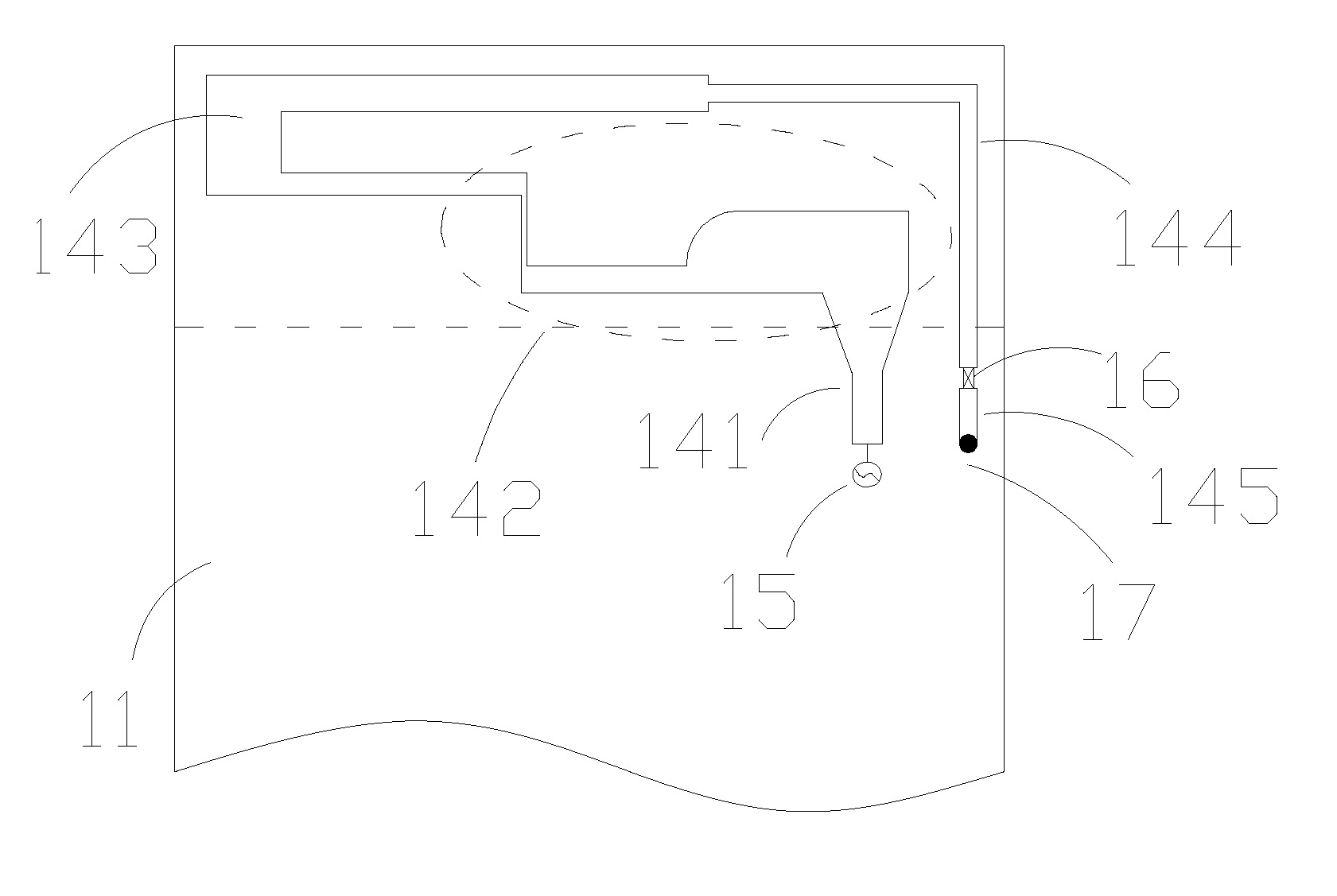
[0022] figure 1 It is a schematic structural diagram of the first embodiment of the frequency reconfigurable built-in antenna of the present invention. It includes a dielectric board 11 , a ground plane 12 , an antenna bracket 13 , a feeding spring 15 , a grounding spring 17 , an antenna pattern 14 and a gate switch 16 . The ground plane 12 is located on the bottom surface of the dielectric plate, where a certain area is corroded, and the antenna support is placed above the corroded area; the antenna pattern 14 is inlaid on the top and side walls of the antenna support, including a feeding arm 141 and a matching tuning arm 142, The U-shaped arm 143, the transition arm 144 and the grounding arm 145. The feeding arm guides electromagnetic energy to the antenna to excite high-frequency current, thereby radiating electromagnetic waves in space. The existence of the U-shaped arm is to reduce the size of the antenna. The gate switch 16 is loaded between the transition arm 143 and t...

no. 2 example

[0032] Figure 6 It is a schematic structural diagram of the second embodiment of the frequency reconfigurable built-in antenna of the present invention. In addition to the structure of the first embodiment, this embodiment adds a branch 641, which can add a frequency band on the basis of the first embodiment, and use it as a Bluetooth or UTMS frequency band.


PUM

PropertyMeasurementUnit
Lengthaaaaaaaaaa
Widthaaaaaaaaaa
Thicknessaaaaaaaaaa

Abstract

The invention relates to a frequency-reconfigured built-in antenna, comprising an antenna stand (13), antenna patterns (14) on the antenna stand and connectors of the antenna patterns, wherein the connectors are electrically connected with a circuit board; the antenna patterns are monopole antenna patterns of which two ends are respectively connected with respective connector; the connector at one end is electrically connected with a feeding terminal on the circuit board, and the connector at the other end is sequentially connected with a gating switch (16) on the circuit board as well as a short-circuit arm and a grounding elastic sheet for regulating frequency on the circuit board. According to the frequency-reconfigured built-in antenna, one antenna pattern can work under a monopole or loop-circuit antenna mode by controlling the gating switch; and the frequency-reconfigured built-in antenna can meet the multi-band working requirement of a handheld device, is simple and compact in structure, and can greatly save antenna space.

Description

technical field [0001] The invention relates to wireless communication, in particular to a frequency reconfigurable built-in antenna, especially applicable to dual-mode or multi-mode mobile phones. Background technique [0002] With the rapid development of information technology, more and more information subsystems are installed on the same wireless communication system, and the increase of information subsystems will inevitably lead to the increase of antenna frequency band and complexity. Looking at the wireless communication market, the thinning and miniaturization of handheld terminals The trend of thinner and smaller miniaturization will inevitably lead to smaller and smaller design space reserved for antennas. Many existing built-in antennas use multiple antenna patterns to meet different frequency requirements. Therefore, although they have multiple frequency bands, these antennas require a large space. How to design multi-frequency band antennas in a limited antenn...

Claims


Application Information

Patent Timeline
IPC IPC(8): H01Q25/04H01Q1/36H01Q23/00
Inventor 丁卓富
Owner GUANGDONG OPPO MOBILE TELECOMM CORP LTD
Why Eureka
Try Eureka