
A multi-mode electronic device

An electronic device and antenna technology, applied in the field of communication, can solve the problems of low-frequency antennas and large antenna space, and achieve the effect of saving antenna space

Active Publication Date: 2018-08-31
LENOVO (BEIJING) LTD
View PDF3 Cites 0 Cited by
  • Summary
  • Abstract
  • Description
  • Claims
  • Application Information

AI Technical Summary

Problems solved by technology

[0004] Since the wavelength of the low-frequency signal is longer than that of the high-frequency signal, the low-frequency antenna part requires a larger antenna space

Method used


Image

  • A multi-mode electronic device
  • A multi-mode electronic device
  • A multi-mode electronic device

Examples


Embodiment Construction

[0021] The following will clearly and completely describe the technical solutions in the embodiments of the present invention with reference to the accompanying drawings in the embodiments of the present invention. Obviously, the described embodiments are only some, not all, embodiments of the present invention. Based on the embodiments of the present invention, all other embodiments obtained by persons of ordinary skill in the art without making creative efforts belong to the protection scope of the present invention.

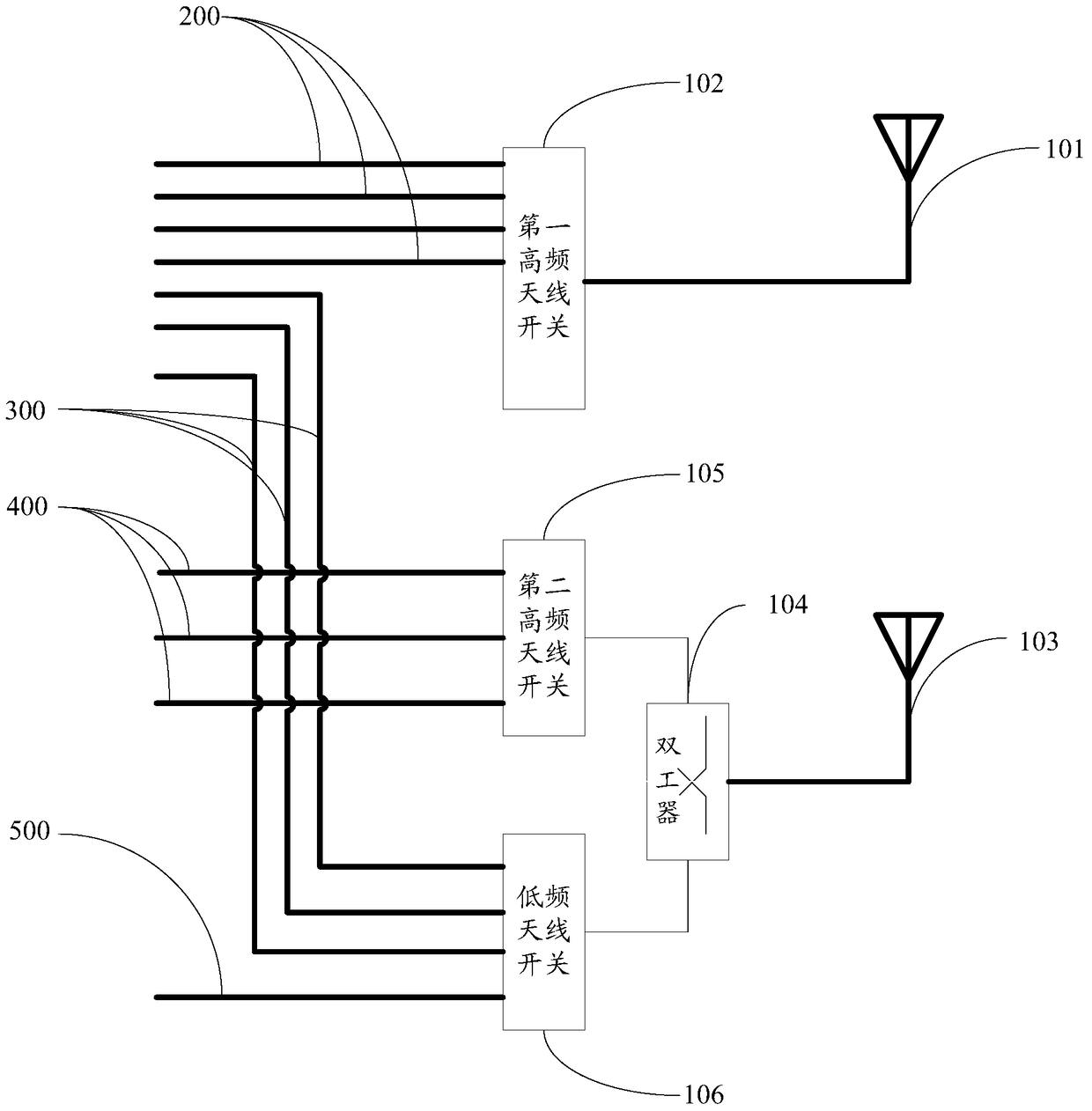
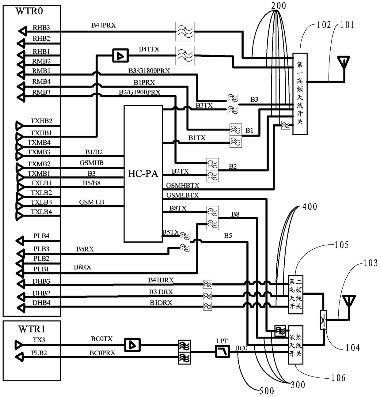
[0022] The embodiment of the present invention discloses a multi-mode electronic device, such as figure 1 As shown, the multi-mode electronic device may include: a first antenna 101, a first high-frequency antenna switch 102, a second antenna 103, a duplexer 104, a second high-frequency antenna switch 105, and a low-frequency antenna switch 106; wherein:

[0023] The first antenna 101 is connected to the first high-frequency antenna switch 102;

[0024] The f...


PUM


Abstract

The invention discloses multi-mode electronic equipment. A first high-frequency antenna switch is connected with a first antenna, the first antenna comprises a high-frequency antenna portion used for transmitting and receiving high-frequency signals with frequency bands being a first frequency band. A second high-frequency antenna switch and a low-frequency antenna switch are connected with a second antenna through a duplexer, the second high-frequency antenna switch is used for connecting a plurality of high-frequency antennas with frequency bands being a second high-frequency band, and the low-frequency antenna switch is used for connecting a plurality of low-frequency antennas with frequency bands being a first low-frequency band and low-frequency antennas with frequency bands being a second low-frequency band. The second antenna comprises a high-frequency antenna portion and a low-frequency antenna portion, the high-frequency antenna portion is used for receiving high-frequency signals with frequency bands being the second high-frequency band, and the low-frequency antenna portion is used for transmitting and receiving low-frequency signals with frequency bands being the first low-frequency band and the second low-frequency band. The multi-mode electronic equipment saves antenna space and solves the problem that in prior art, due to the fact that each antenna comprises a high-frequency antenna portion and a low-frequency antenna portion, a large antenna space is occupied.

Description

technical field [0001] The present invention relates to the technical field of communication, and more specifically relates to a multi-mode electronic device. Background technique [0002] A multi-mode electronic device refers to an electronic device that can support multiple network standards, for example, a multi-mode mobile phone that can support WCDMA, CDMA, GSM, and LTE. [0003] A multi-mode electronic device generally includes two antennas, and each antenna includes a high-frequency antenna part and a low-frequency antenna part. Wherein, the first antenna is respectively connected to the first high-frequency antenna switch and the first low-frequency antenna switch through a duplexer, and is used to transmit and receive high-frequency signals whose frequency band is the first high-frequency band and low-frequency signals whose frequency band is the first low-frequency band ; The second antenna is respectively connected to the second high-frequency antenna switch and ...

Claims


Application Information

Patent Timeline
Patent Type & Authority Patents(China)
IPC IPC(8): H04W88/06H04M1/02
Inventor 霍彬
Owner LENOVO (BEIJING) LTD
Learn More