Antenna structure and communication apparatus
A technology of antenna structure and communication device, which is applied in the direction of antenna support/installation device, antenna, resonant antenna, etc., and can solve problems such as development bottlenecks
- Summary
- Abstract
- Description
- Claims
- Application Information
AI Technical Summary
Problems solved by technology
Method used
Image
Examples
no. 2 example
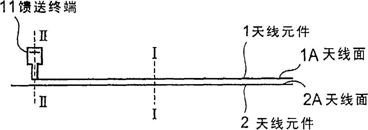
[0096] 12 to 14 show a second embodiment according to the invention. The feeding terminal 12 according to the second embodiment uses a spring connector 12A as a part of the feeding terminal 12 . The antenna element 1 is connected to the wireless circuit of the substrate 20 through a spring connector 12A (cf. Figure 5 ). Other configurations and operating effects are based on Figure 5 The configuration and operation effects are the same as those of the illustrated embodiment, and detailed explanations are omitted here.
no. 3 example
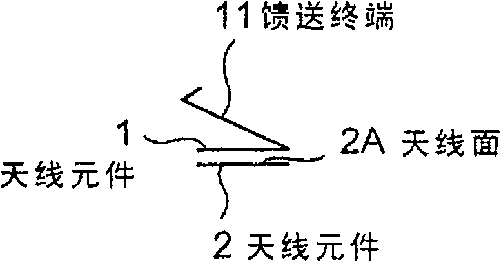
[0098] Figure 15 A third embodiment of the invention is shown. In the third embodiment, a feeding terminal 13 forming a part of feeding means is provided in the antenna element 1 . The feeding terminal 13 is planar. The substrate 20 is provided with a planar feed connector 14 . The feed connector 14 is spring-shaped, and the tip of the feed connector 14 is bent into a V shape.
[0099] According to the third embodiment, since the feed connector 14 forming a part of the connection unit is connected to the feed terminal 13 , the wireless circuit of the substrate 20 is connected through the feed connector 14 . The feed connector 14 is pushed toward the feed terminal 13 . Other configurations and operating effects are based on Figure 5 The configuration and operation effects of those of the illustrated embodiment are the same. Therefore, detailed description is omitted here.
no. 4 example
[0101] Figures 16A to 16C , 17 and 18 show a fourth embodiment of the present invention. In a fourth embodiment, one or both of the two antenna elements 1 and 2 according to the first embodiment are curved. For example, in Figure 16C In the antenna element 2 shown, the planar pattern of the antenna element 2 is meandered.
[0102] In the fourth embodiment, the meandering antenna element 2 enables setting a desired frequency. Such as Figure 16C As shown, when the antenna element 2 is bent in a meandering pattern, the actual size of the antenna element 2 can be compared to Figure 1C The case shown in is longer (longer wavelength), thus reducing the frequency.
[0103] In another variation, the antenna elements may be curved in a three-dimensional array. The remaining configuration and operation effects are the same as Figure 5 The configuration and operation effects of those of the illustrated embodiment are the same. Therefore, detailed description is omitted here....
PUM
 Abstract
Description
Claims
Application Information
 - R&D Engineer
- R&D Manager
- IP Professional
- Industry Leading Data Capabilities
- Powerful AI technology
- Patent DNA Extraction
Browse by: Latest US Patents, China's latest patents, Technical Efficacy Thesaurus, Application Domain, Technology Topic, Popular Technical Reports.
© 2024 PatSnap. All rights reserved.Legal|Privacy policy|Modern Slavery Act Transparency Statement|Sitemap|About US| Contact US: help@patsnap.com


