
Antenna structure and electronic device

an antenna structure and electronic device technology, applied in the direction of individual energised antenna arrays, resonant antennas, antenna earthings, etc., can solve the problems of occupying more configurational space inside the laptop, affecting the appearance of the laptop, and the overall extension length of the antenna structure to be too large. , to achieve the effect of saving the configurational space of the antenna structur

Active Publication Date: 2020-08-25
PEGATRON
View PDF10 Cites 0 Cited by
  • Summary
  • Abstract
  • Description
  • Claims
  • Application Information

AI Technical Summary

Benefits of technology

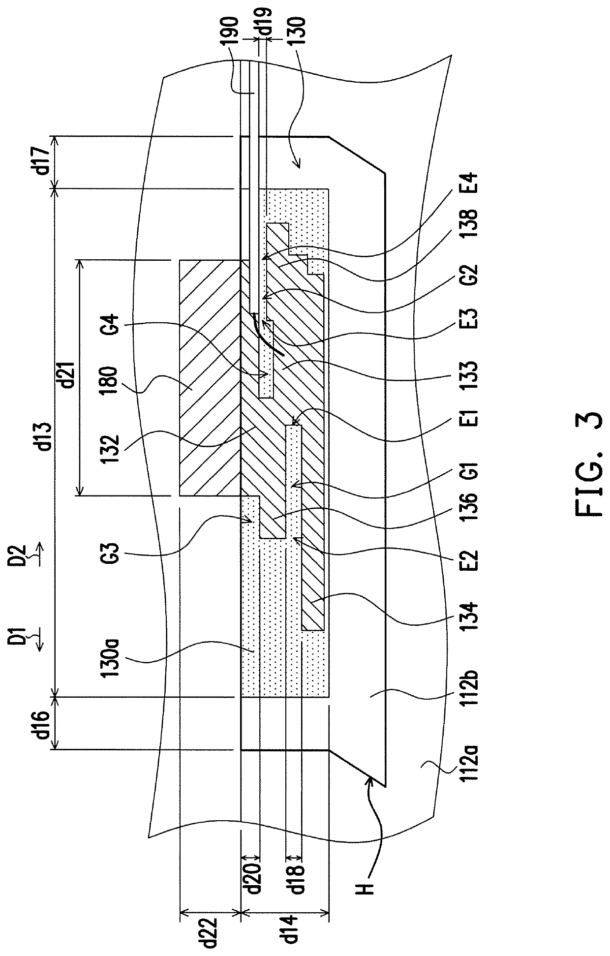
The invention provides an antenna structure that can save space by having three antennas integrated into one single grounding portion, one single feeding portion, and three radiating portions. This results in a compact antenna structure that does not require a large amount of space. The gaps between the different parts of the antenna structure also contribute to the savings of space, as they allow for independent extension of the different parts of the antenna. Overall, this invention provides a way to make antennas more efficient in terms of space utilization.

Problems solved by technology

However, such configuration influences the appearance of the laptop.
However, the plurality of radiating portions are generally sequentially extended in a continuous manner, which causes an overall extension length of the antenna structure to be overly large and occupies more configurational space inside the laptop.
Therefore, how to configure the antenna structure to exhibit excellent capacity of signal reception and transmission without influencing the appearance of the laptop and save the configurational space of the antenna structure is one of the important issues in designing an antenna of laptops.

Method used


Image

  • Antenna structure and electronic device
  • Antenna structure and electronic device
  • Antenna structure and electronic device

Examples


Embodiment Construction

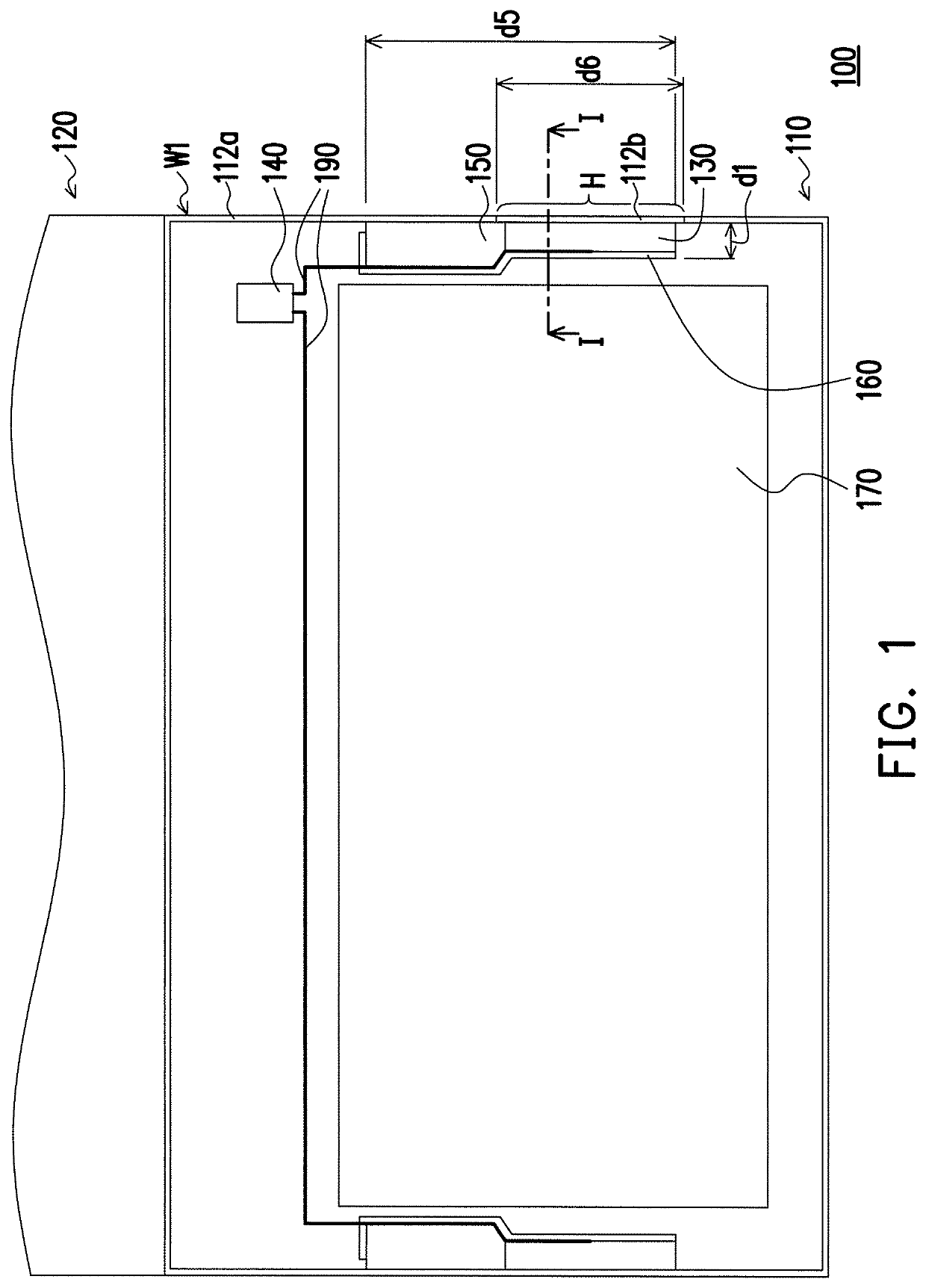
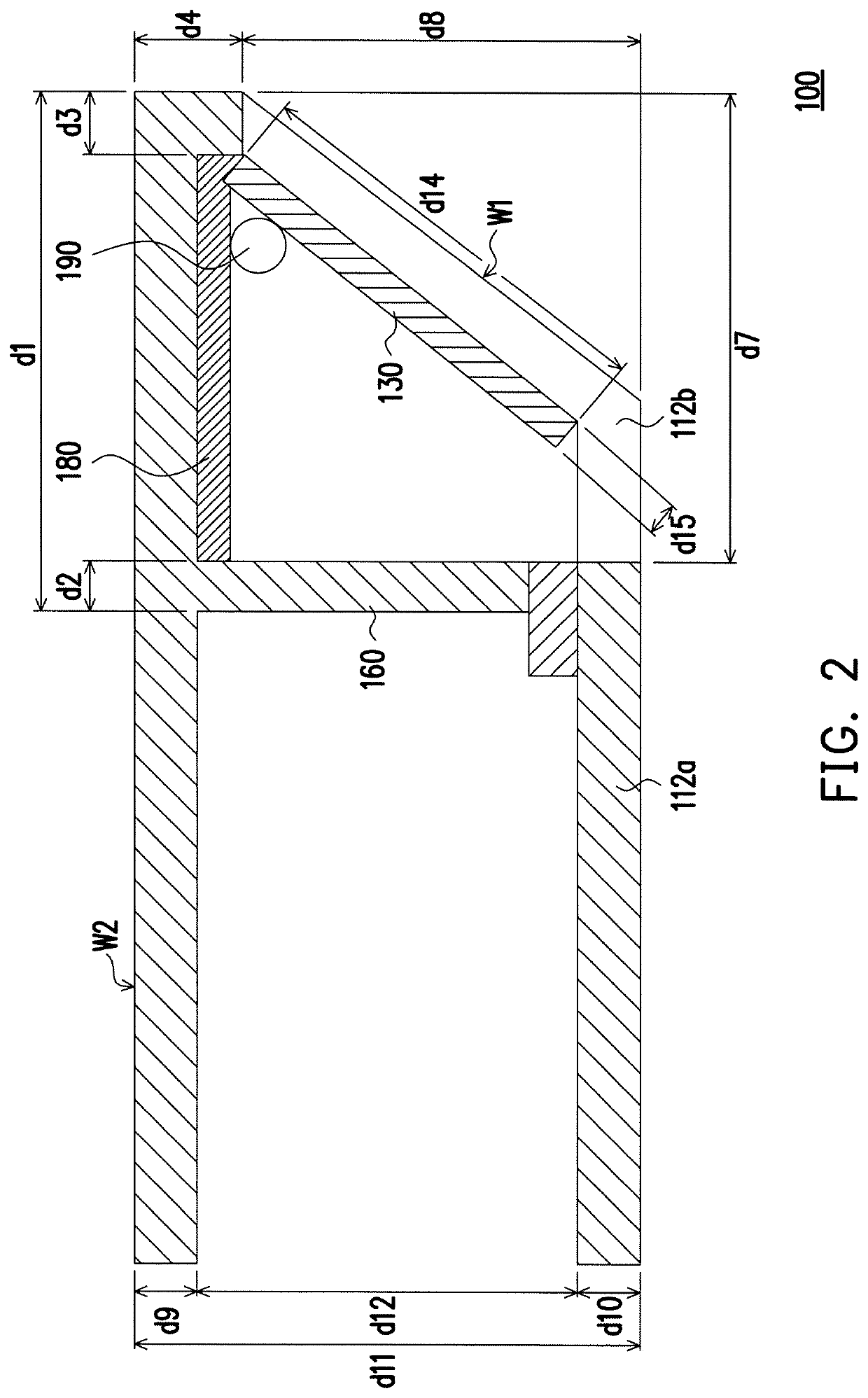
[0029]FIG. 1 is a schematic diagram illustrating part of components of an electronic device according to an embodiment of the invention. FIG. 2 is a cross-sectional diagram illustrating part of components of the electronic device of FIG. 1 along line I-I. Referring to FIG. 1 and FIG. 2, an electronic device 100 of the present embodiment is, for example, a laptop and includes a device body 110, a display 120, at least one antenna structure 130 (two antenna structures are illustrated), and a wireless signal processing module 140. As shown in FIG. 1, the antenna structure 130 of the present embodiment is illustrated as two antenna structures, and the two antenna structures 130 are respectively disposed at two opposite sides of the device body 110. However, the invention is not limited hereto, and it is also possible to dispose only one antenna structure 130 at the device body 110.

[0030]The device body 110 is, for example, a host of the laptop and includes a housing 112a, and the housin...


PUM


Abstract

An antenna structure including a grounding portion, a feeding portion, a first radiating portion, a second radiating portion, and a third radiating portion is provided. The first radiating portion is connected to the feeding portion, wherein the first radiating portion is adapted to generate a low-frequency resonant mode. The second radiating portion is connected to the feeding portion, wherein a first gap is formed between the first radiating portion and the second radiating portion, and the second radiating portion is adapted to generate a first high-frequency resonant mode. The third radiating portion is connected to the feeding portion, wherein a second gap is formed between the third radiating portion and the grounding portion, and the third radiating portion is adapted to generate a second high-frequency resonant mode. In addition, an electronic device including the antenna structure is also provided.

Description

CROSS-REFERENCE TO RELATED APPLICATION[0001]This application claims the priority benefit of Taiwan application serial no. 106109884, filed on Mar. 24, 2017. The entirety of the above-mentioned patent application is hereby incorporated by reference herein and made a part of this specification.BACKGROUNDField of the Invention[0002]The invention relates to an antenna structure and an electronic device including the same, and in particular, to an antenna structure including a plurality of radiating portions and an electronic device including the same.Description of Related Art[0003]With the advance of technologies, the modes of communications for the general public have gradually become wireless. For example, smartphones, tablet computers, and laptops having wireless networking functions all fall in the scope of wireless communication, and wireless communication usually requires antennas for transmitting signals.[0004]In terms of laptops, the housing is commonly formed of a metallic mat...

Claims


Application Information

Patent Timeline
Patent Type & Authority Patents(United States)
IPC IPC(8): H01Q1/22H01Q9/04H01Q9/42H01Q5/307H01Q5/371H01Q21/06
CPCH01Q1/2266H01Q9/0421H01Q1/2291H01Q5/371H01Q9/42H01Q21/065H01Q5/307H01Q1/36H01Q1/48H01Q1/50H01Q13/10
Inventor WU, CHIEN-YIWU, CHAO-HSUKO, CHING-HSIANGHUANG, SHIH-KENGWU, CHENG-HSIUNGLI, YA-JYUN
Owner PEGATRON
Learn More