
Clock management unit of RFID tag chip

A technology of clock management unit and RFID tag, which is applied to record carriers used in machines, instruments, computer components, etc., can solve problems such as peak power consumption cannot be reduced, power consumption is generated, etc., to reduce peak power consumption and average The effect of power consumption

Inactive Publication Date: 2011-08-17
SHENZHEN ZHENGDONGYUAN TECH CO LTD
View PDF3 Cites 7 Cited by
  • Summary
  • Abstract
  • Description
  • Claims
  • Application Information

AI Technical Summary

Problems solved by technology

In the RFID tag chip, many modules are triggered at the same time and work at the same time, and each module will have power consumption. The introduction of the gating clock unit has reduced the average power consumption, but the peak power consumption still cannot be reduced.

Method used


Image

  • Clock management unit of RFID tag chip
  • Clock management unit of RFID tag chip
  • Clock management unit of RFID tag chip

Examples


Embodiment Construction

[0015] The present invention will be further elaborated below in conjunction with the accompanying drawings.

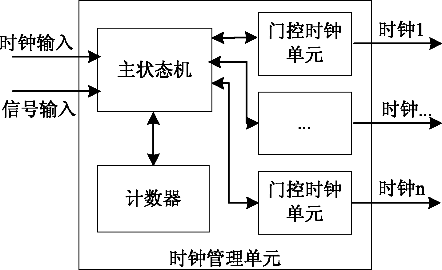
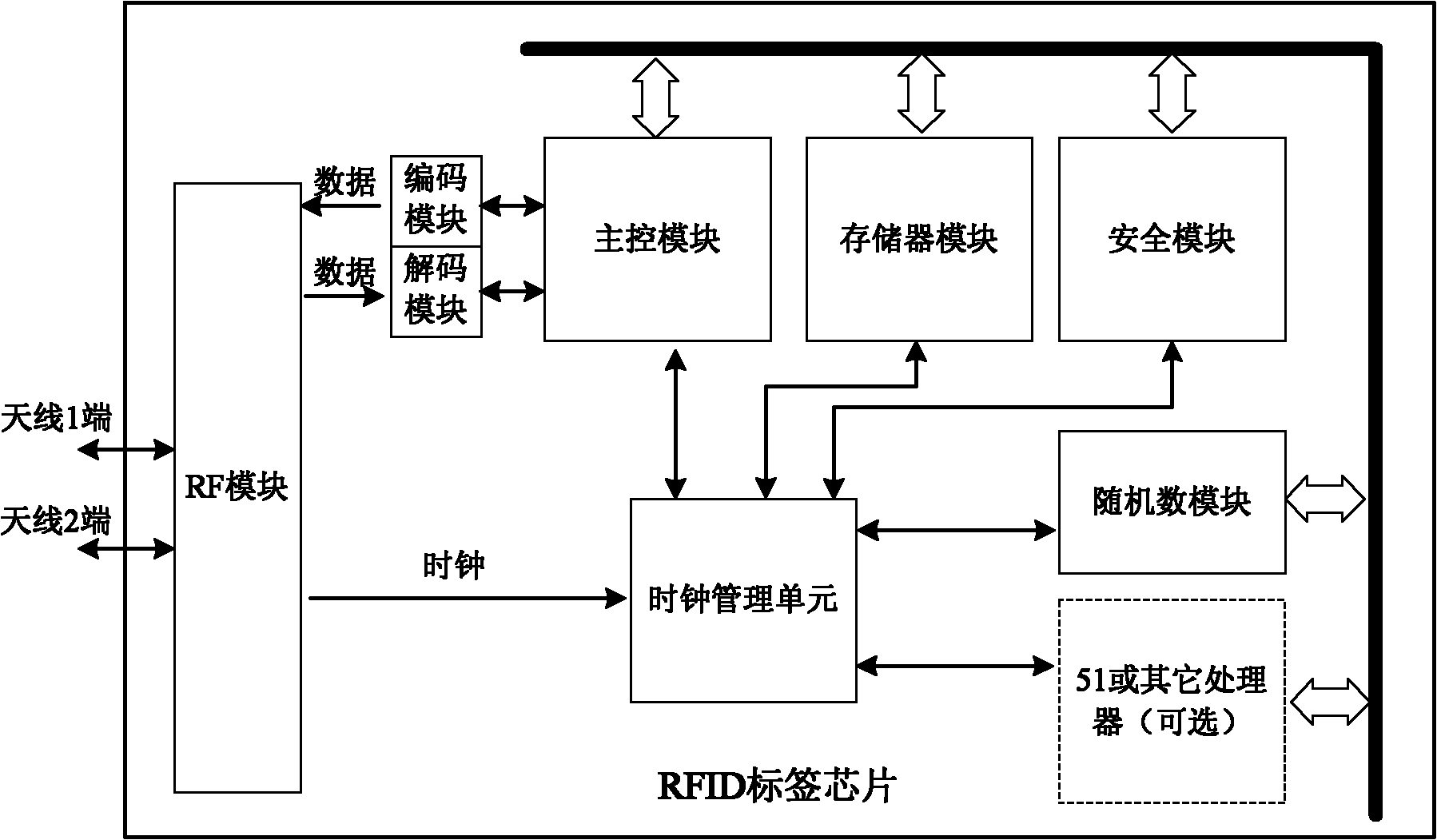
[0016] Such as figure 1 As shown, the clock management unit of the RFID tag chip of the present invention includes a main state machine, a counter and several gating clock units. Such as figure 2 As shown, the external radio frequency signal is input to the RF module through the two ports of the antenna, and the clock signal and data signal are demodulated by the RF module. The clock signal is directly input to the clock management unit, and the data signal is input to the main control module through the decoding module. The control module communicates with the memory module, security module, random number and other modules through the bus, and at the same time, the working state variables of these modules are connected to the clock management unit as input signals. The clock management unit outputs a clock signal, which is directly connected to each module as the ...


PUM


Abstract

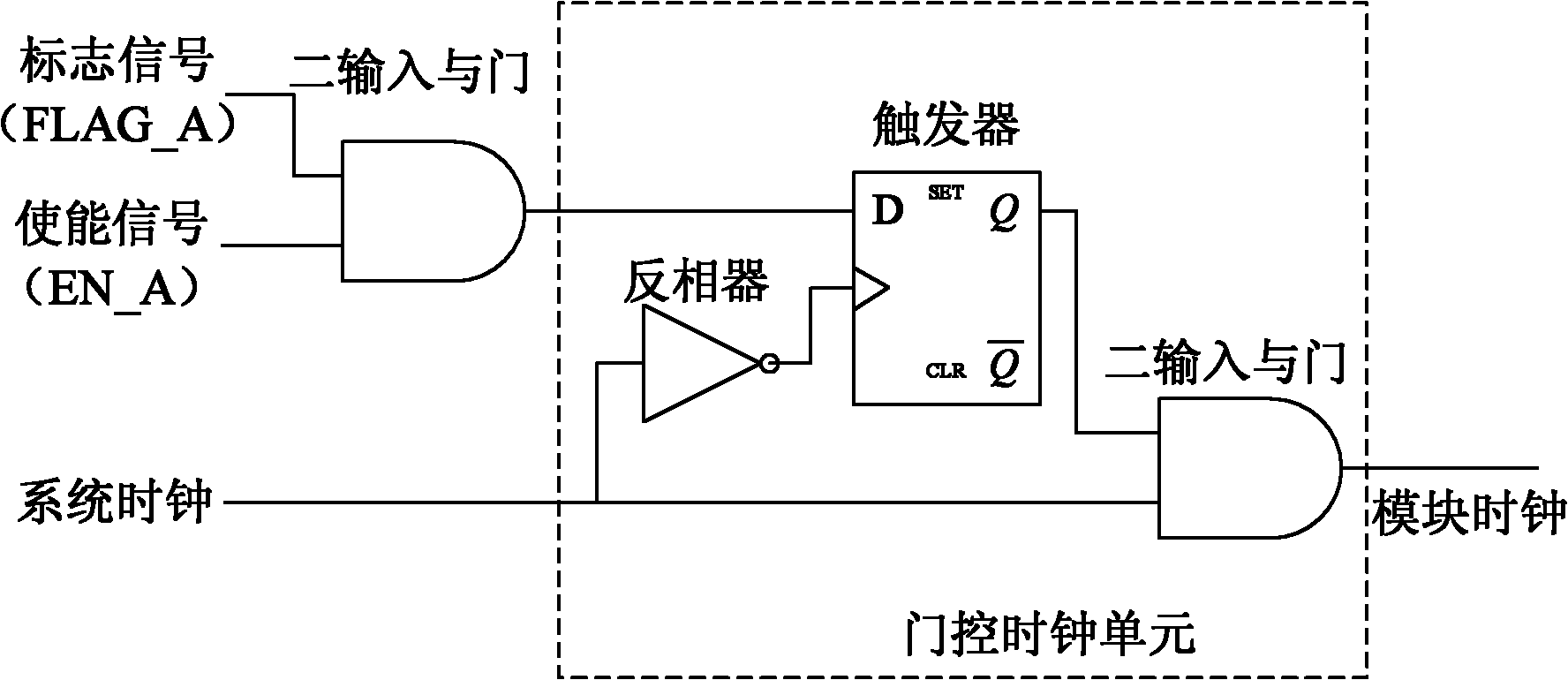
The invention discloses a clock management unit of a RFID (radio frequency identification) tag chip which can reduce power consumption and peak power consumption of the RFID tag chip. The clock management unit of the RFID tag chip comprises a main state machine, a counter and a plurality of gating clock units, wherein the main state machine analyzes the state of each functional unit of the tag chip, judges moments when a plurality of functional units are woken at the same time and a plurality of operations are executed at the same time, and further judges which functional units are still unnecessary, sets a clock enable signal of the functional units which can be stopped to zero, and separates the operations of the plurality of functional units which are independent to each other and enable registers to turn over synchronously; the counter is used for helping control on the input signal, and helping the main state machine to move up some operations of the functional units which are independent to each other and enable registers to turn over synchronously for several clocks and delay some operations of the same for several clocks; the gating clock units are used for instantiating the enable signals and system clock signals of each functional unit, and taking the instantiated output clock as a control clock for controlling the action of each functional unit.

Description

technical field [0001] The invention relates to an RFID tag chip clock management unit, in particular to an RFID tag chip clock management unit capable of controlling and reducing the power consumption and peak power consumption of the RFID tag chip. Background technique [0002] In the process of chip design, with the increase of operating frequency and the expansion of system modules, the increase of the total power consumption of the chip has brought many negative effects, which directly leads to serious heat dissipation problems and greatly limits the improvement of system performance. [0003] The power supply of the RFID tag chip comes from the induction magnetic field continuously provided by the reader. The requirement of low power consumption is more obvious. At the same time, if the peak power consumption is too large, the working voltage of the chip will be lowered instantly, causing the switch tube to flip incorrectly. Even the communication process of RFID is in...

Claims


Application Information

Patent Timeline
IPC IPC(8): G06K19/073
Inventor 胡建国丁颜玉郑俊辉王德明谭洪舟张俊
Owner SHENZHEN ZHENGDONGYUAN TECH CO LTD
Learn More