
Magnetic induction heating method and special devices

A heating method and special device technology, applied in the field of magnetic eddy current induction, can solve the problems of high power consumption and small application range, and achieve the effects of low power consumption, wide application range and convenient use

Active Publication Date: 2011-08-03
张洪军 +1
View PDF7 Cites 16 Cited by
  • Summary
  • Abstract
  • Description
  • Claims
  • Application Information

AI Technical Summary

Problems solved by technology

The power consumption is still high, and the application range is small, such as the induction cooker is only used to heat food

Method used


Image

  • Magnetic induction heating method and special devices
  • Magnetic induction heating method and special devices
  • Magnetic induction heating method and special devices

Examples


Embodiment 1

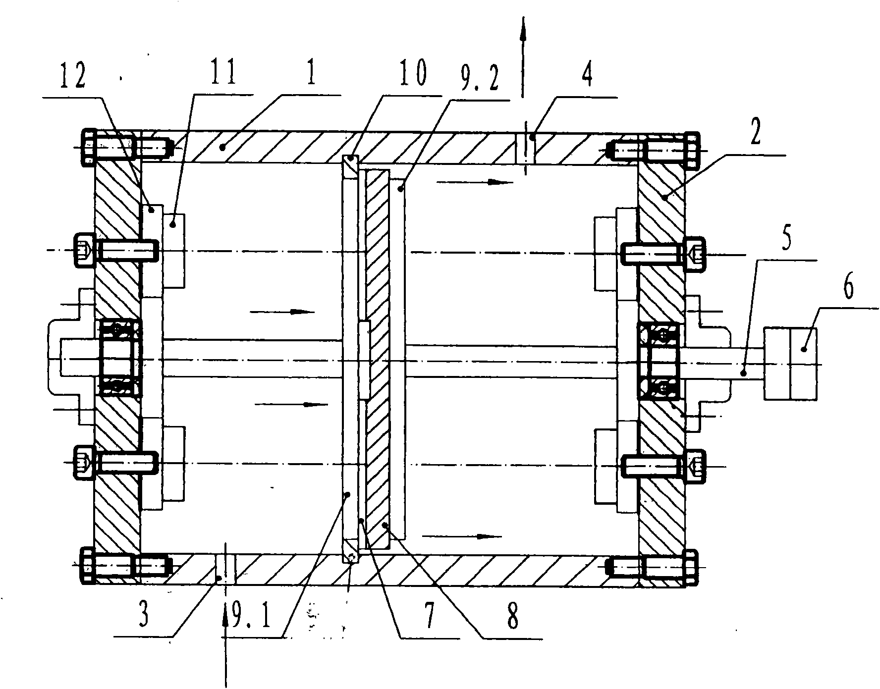
[0015] figure 1 Shown is a special device for magnetic induction heating of the present invention, which is mainly composed of a cylindrical barrel 1, which can be made of metal or other materials. Both ends of the barrel body 1 are provided with barrel covers 2 to form a closed cavity. A rotating shaft 5 is arranged at the center line of the two bucket covers 2, and the rotating shaft 5 is arranged on the two bucket covers 2 through rolling bearings. A metal turbine 8 with a spiral groove 7 is arranged in the middle of the rotating shaft 5. The metal turbine 8 is covered with a metal splint A9.1 on the front and a metal splint B9.2 on the back. The metal splint A9.1 is provided with a spiral Slot 7 communicates with the water eye. A water seal 10 is provided between the outer end of the metal splint A9.1 and the barrel 1, so that two cavities are formed inside the barrel 1. The cavity on the side of the metal splint A9.1 is the water inlet cavity, and the other The side is t...

Embodiment 2

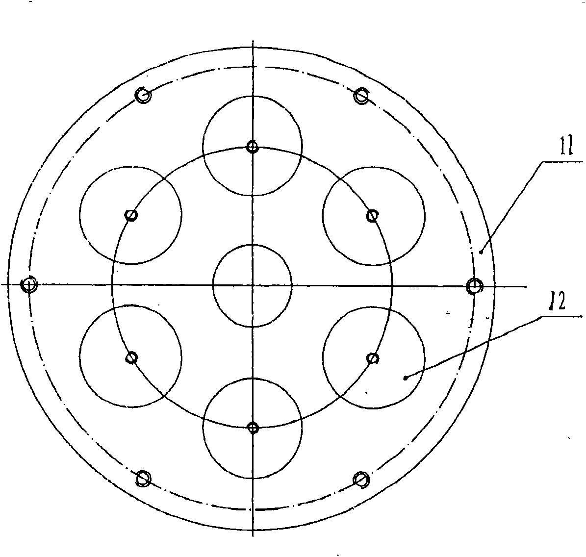
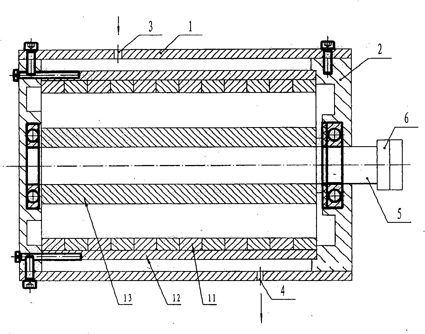
[0018] image 3 Shown here is another special device for magnetic induction heating of the present invention, which is mainly composed of a cylindrical barrel 1 with lids 2 provided at both ends of the barrel 1 to form a closed cavity. A rotating shaft 5 is arranged at the center line of the two bucket covers 2, and the rotating shaft 5 is arranged on the two bucket covers 2 through rolling bearings. A circular barrel-shaped metal barrel 13 is arranged longitudinally on the periphery of the rotating shaft 5, and the metal barrel 13 should have a certain thickness to ensure the cutting force to the magnetic lines of force. The rotating shaft 5 is driven by the external motor 6 to rotate at a high speed through a clutch, thereby driving the metal barrel 13 on it to rotate at a high speed. Such as Figure 4 As shown, arc-shaped permanent magnets are uniformly arranged on the inner wall of the barrel 1 through the magnetic field closing body 12, the magnetic field closing body 12 ...


PUM


Abstract

The invention discloses a magnetic induction heating method and special devices, which belong to the field of electromagnetic eddy current induction. A high-strength magnetic field is provided by a correspondingly arranged permanent magnet; a metal body rotates at a high speed in the magnetic field to cut a magnetic line of force so as to be heated through an eddy current effect; and the heated metal body outputs heat energy through a fluid medium. In a device, a rotating shaft in a barrel body is provided with a metal turbine with a spiral groove; the metal turbine is covered by metal clamping plates; and a barrel cover at the periphery of the rotating shaft is provided with the corresponding permanent magnet. In another device, the rotating shaft in the barrel body is provided with a metal barrel; and the inner wall of the barrel body is provided with the permanent magnet. High-temperature hot water or hot steam is produced through heat exchange to output heat energy. The invention can be widely applied to household heating or industrial heat supply and air supply, and has the advantages of low electric energy consumption, wide application range, convenience for use, economy andenvironmental protection.

Description

Technical field [0001] The invention belongs to the field of magnetic eddy current induction, in particular to a method for heating through the magnetic eddy current effect. The invention also relates to a special device for the magnetic induction heating method. Background technique [0002] At present, industrial boilers or household heating are still mainly steam boilers, which consume a lot of energy and cause serious pollution. With the application of electromagnetic equipment, electromagnetic heating devices have also emerged. The current electromagnetic heating devices generally generate high-speed changing magnetic fields through voltages and coils. The lines of magnetic force pass through the metal to generate eddy current effects to make the metal heat. The consumption of electric energy is still high, and the application range is small, such as induction cooker only used for heating food. Summary of the invention [0003] The purpose of the present invention is to pro...

Claims


Application Information

Patent Timeline
IPC IPC(8): H05B6/10H05B6/02
Inventor 张洪军金华君
Owner 张洪军
Learn More