
Rotational coordinate transformation based current decoupling control method for three-phase grid-connected inverter

A technology of three-phase current and synchronous rotating coordinates, applied in the direction of converting AC power input to DC power output, output power conversion device, electrical components, etc., can solve the problem of control system cost and control performance disadvantages, large amount of state variable sampling, Differential operation interference and other problems can be achieved to enhance the independent control ability, the control method is simple and feasible, and the control design is simplified

Active Publication Date: 2013-03-13
ZHEJIANG UNIV
View PDF3 Cites 0 Cited by
  • Summary
  • Abstract
  • Description
  • Claims
  • Application Information

AI Technical Summary

Problems solved by technology

Traditional decoupling operations often select state variables from the system and use them directly for decoupling items. There are various problems such as large sampling amount of state variables, large calculation amount, and large interference of differential operations, which have great impact on the cost and control performance of the control system. had an adverse effect on

Method used


Image

  • Rotational coordinate transformation based current decoupling control method for three-phase grid-connected inverter
  • Rotational coordinate transformation based current decoupling control method for three-phase grid-connected inverter
  • Rotational coordinate transformation based current decoupling control method for three-phase grid-connected inverter

Examples


Embodiment Construction

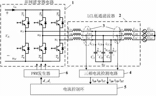
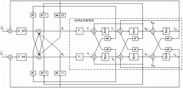
[0042] figure 1 Shown is the main circuit and control block diagram of the grid-connected inverter. It includes a three-leg three-phase inverter circuit 1 based on high-frequency switches (in the illustration, the three-phase inverter is a voltage source type three-leg six-switch inverter, using IGBT as a power switch), used for inverting and paralleling LCL low-pass filter for grid connection operation 2, two sets of current transmitters for three-phase LCL low-pass filter inverter side inductance current detection and grid side inductance current detection 3, three-phase current detection circuit 4, current control loop 5 and PWM pulse generator 6, where current controls loop 5 (see Figure 4 ) contains current weighted average calculation 7, error calculation and proportional integral regulator 8 and decoupling operation 9.

[0043] The current decoupling control method of the three-phase grid-connected inverter based on the synchronous rotating coordinate system of the p...


PUM


Abstract

The invention discloses a rotational coordinate transformation based current decoupling control method for a three-phase grid-connected inverter. With regard to a grid-connected inverter with an LCL (Inductor Capacitor Inductor) filter, an inversion three-phase output current signal and a grid-side three-phase current signal are transformed into two groups of orthogonal current signals in a synchronous rotation coordinate system through adopting coordinate transformation, the two groups of orthogonal current signals are subjected to the calculation of weighted average to be used as an inverter current controlled feedback signal and an inverter current controlled decoupling signal under a rotational coordinate system, the feedback signal is compared with a control given signal to obtain an error signal, and the obtained error signal is subjected to proportional-integral regulation and then is subjected to a combined operation with the decoupling signal to obtain a pulse duty-ratio signal for controlling a three-phase inverter switch to operate under the rotational coordinate system, so that output current waveform and amplitude control of the grid-connected inverter can be realized. Through adopting the method disclosed by the invention, the signal coupling problem existing in three-phase current control of the LCL filter three-phase grid-connected inverter can be effectively solved, the capacity of independently controlling each phase of output current is enhanced, and the favorable output current waveform of a grid-connected system can be achieved.

Description

technical field [0001] The invention relates to a control method for a three-phase grid-connected inverter, in particular to a current decoupling control method for a three-phase grid-connected inverter based on rotational coordinate transformation. Background technique [0002] Three-phase grid-connected inverter power supply with LCL filtering, its main circuit and control block diagram refer to figure 1 As shown, it usually includes a three-phase three-phase inverter circuit based on high-frequency switches, a three-phase LCL low-pass filter (three-phase symmetry) for inverter grid-connected connection, a three-phase current transmitter and a current detection circuit And the inverter controller, wherein the inverter controller includes a current control loop and a PWM pulse generator, and controls the output current during grid-connected operation to ensure the power quality of grid-connected power generation. Since the three-phase currents are interrelated, the three-p...

Claims


Application Information

Patent Timeline
Patent Type & Authority Patents(China)
IPC IPC(8): H02J3/38H02M7/5395
Inventor 沈国桥张俊徐德鸿
Owner ZHEJIANG UNIV
Learn More