Automatic optical distribution frame, and calibration method and system thereof
A technology of automatic wiring and optical fiber, applied in the field of communication, can solve the problems of increasing insertion loss, increasing cost, increasing packaging cost, etc., and achieve the effect of improving calibration accuracy, reducing complexity, and reducing cost
- Summary
- Abstract
- Description
- Claims
- Application Information
AI Technical Summary
Problems solved by technology
Method used
Image

Examples
Embodiment 1
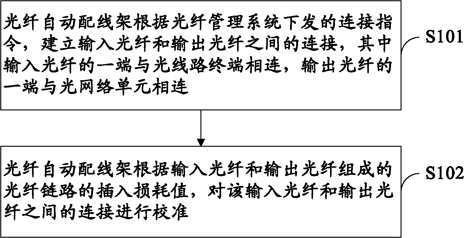
[0037] The method for calibrating the optical fiber automatic distribution frame provided by Embodiment 1 of the present invention, such as figure 1 As shown, the method steps include:
[0038] S101. The optical fiber automatic distribution frame establishes the connection between the input optical fiber and the output optical fiber according to the connection instruction issued by the optical fiber management system, wherein one end of the input optical fiber is connected to the optical line terminal, and one end of the output optical fiber is connected to the optical network unit.
[0039] Specifically, AODF searches for the deflection angle required by the MEMS micro-mirror corresponding to the connection between the input fiber and the output fiber according to the connection command issued by the FMS (Fiber Management System, fiber management system), calculates the control signal according to the deflection angle, and controls the The MEMS micromirror is rotated to a spe...
Embodiment 2
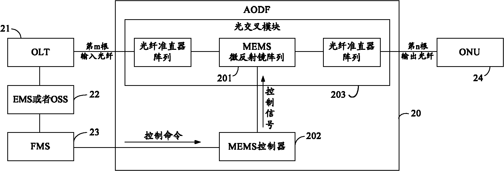
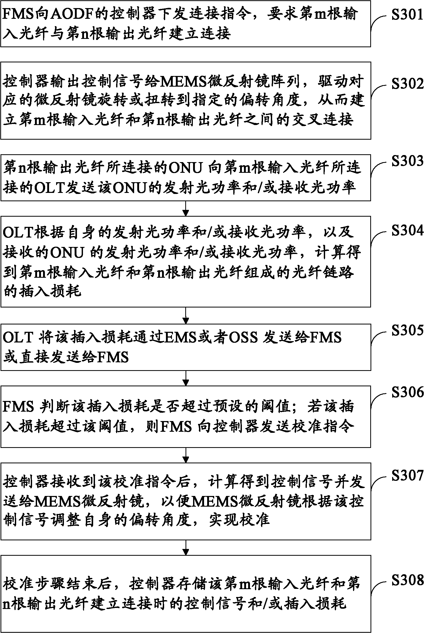
[0045] For the AODF calibration method provided by the embodiment of the present invention, refer to figure 2 , image 3 Be explained. in, figure 2 It is a schematic structural diagram of the AODF system corresponding to the method of this embodiment; image 3 It is a flow chart of the method steps in this embodiment.
[0046] Such as figure 2 As shown, the AODF 20 includes an optical crossover module 203 and a MEMS controller 202, and the mth input optical fiber connected to the OLT 21 is connected to the ONU 24 connected to the nth input optical fiber through the AODF 20, wherein the other end of the OLT 21 It is connected with EMS or OSS22, one end of EMS or OSS 22 is connected with FMS 23, and the other end of FMS 23 is connected with MEMS controller 202 in AODF 20, wherein optical cross module 203 includes MEMS micro-mirror array 201.
[0047] S301. The FMS 23 issues a connection instruction to the controller 202 of the AODF 20, requiring the m th input optical fi...
Embodiment 3
[0072] For the AODF calibration method provided by the embodiment of the present invention, refer to Figure 4 , Figure 5 Be explained. in, Figure 4 It is a schematic structural diagram of the AODF system corresponding to the method of this embodiment; Figure 5 It is a flow chart of the method steps in this embodiment.
[0073] S501. The FMS 23 issues a connection instruction to the controller 202 of the AODF 20, requiring the mth input optical fiber to establish a connection with the nth output optical fiber.
[0074] S502, the controller 202 finds the deflection angle value or the control signal (first control signal) value required by the corresponding micromirror of the MEMS micromirror array 201 when the two optical fiber connections are established in the pre-calibration information stored internally, Then calculate the control signal value according to the deflection angle value or directly output the control signal to the MEMS micro-mirror array 201 according to...
PUM
 Abstract
Description
Claims
Application Information
 - R&D
- Intellectual Property
- Life Sciences
- Materials
- Tech Scout
- Unparalleled Data Quality
- Higher Quality Content
- 60% Fewer Hallucinations
Browse by: Latest US Patents, China's latest patents, Technical Efficacy Thesaurus, Application Domain, Technology Topic, Popular Technical Reports.
© 2025 PatSnap. All rights reserved.Legal|Privacy policy|Modern Slavery Act Transparency Statement|Sitemap|About US| Contact US: help@patsnap.com