
Energy-saving boiler

An energy-saving pot and section pot technology, applied in the fields of energy-saving steamers and energy-saving stew pots, can solve the problems of little difference in structure, low heat exchange efficiency, improved thermal efficiency, etc., and achieve the advantages of beautiful appearance, fuel saving and CO2 emission reduction. Effect

Inactive Publication Date: 2011-07-27
JIEYANG RENYUDE ENERGY SAVING TECH
View PDF11 Cites 5 Cited by
  • Summary
  • Abstract
  • Description
  • Claims
  • Application Information

AI Technical Summary

Problems solved by technology

[0002] At present, domestic and foreign household steaming (stewing) pots have little difference in basic structure. Most of them are cylindrical pans with two or three steamer grates (or a set of stewing pots) and lids. The commercial specifications are larger. There are more grates in the steamer (or a larger pot for stewing and stewing), cylindrical or square, and the bottom of the pot is basically flat. Generally, steaming buns, steaming rice or stewing requires a long time to turn on the stove. , due to the flat bottom and small heating surface, only a part of the high-temperature flame flue gas heat flow of the stove exchanges heat with the water in the steamer, and most of the high-temperature flame flue gas heat flow overflows from the bottom of the pot due to the small heat transfer area and short heat transfer time. In the surrounding atmosphere, its heat transfer efficiency is low, only 40~45%, which belongs to high energy consumption and high CO 2 emission
Some people tried to change the flat bottom to a concave bottom or add some short fins to the bottom of the pan, but the thermal efficiency was only slightly improved, and the state of high energy consumption and high emission could not be changed at all.

Method used


Image

  • Energy-saving boiler
  • Energy-saving boiler
  • Energy-saving boiler

Examples


Embodiment 1

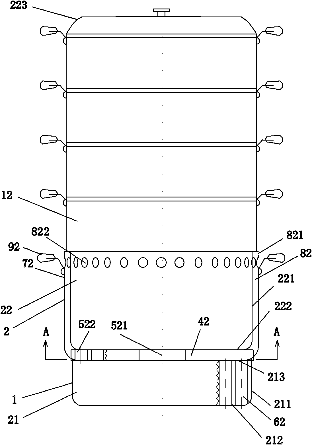
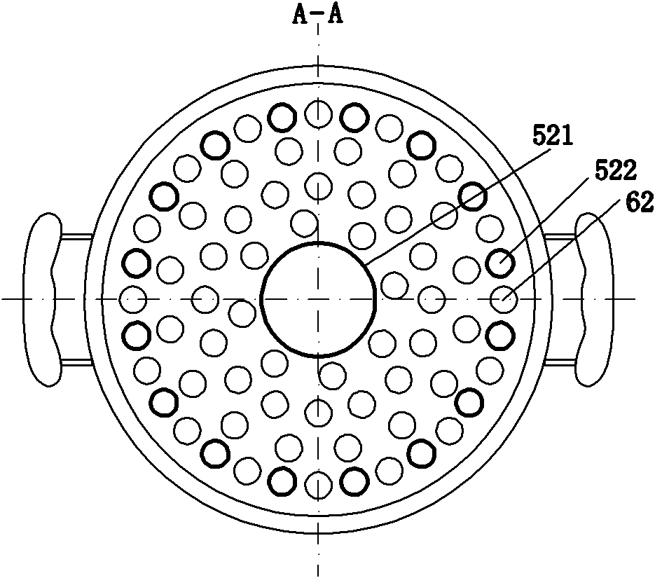
[0017] Embodiment 1, two-stage energy-saving steamer. refer to figure 1 , figure 2 The pot body 1 of the second-stage energy-saving steamer includes a lower pot 21 and an upper pot 22, an annular cavity 42 is arranged between the top surface 213 of the lower pot 21 of the second-stage pot 2 and the bottom surface 222 of the upper pot 22, and the lower pot 21 Between the upper pot 22, a central connecting pipe 521 and 16 communicating pipes 522 uniformly distributed around the outermost circle of the central axis are provided along the central axis of the pot. Outside the shell 221 of the upper pot 22 of the second pot, Outer ring 72 with equal gap with pot shell 221, handle 92 is arranged on the upper part of outer ring 72, outer ring 72 communicates with annular cavity 42 to form flue gas heat flow heat exchange discharge channel 82, and its outlet end is provided with open outer outer ring exhaust Port 821 or a plurality of closed side exhaust holes 822 uniformly distribu...

Embodiment 2

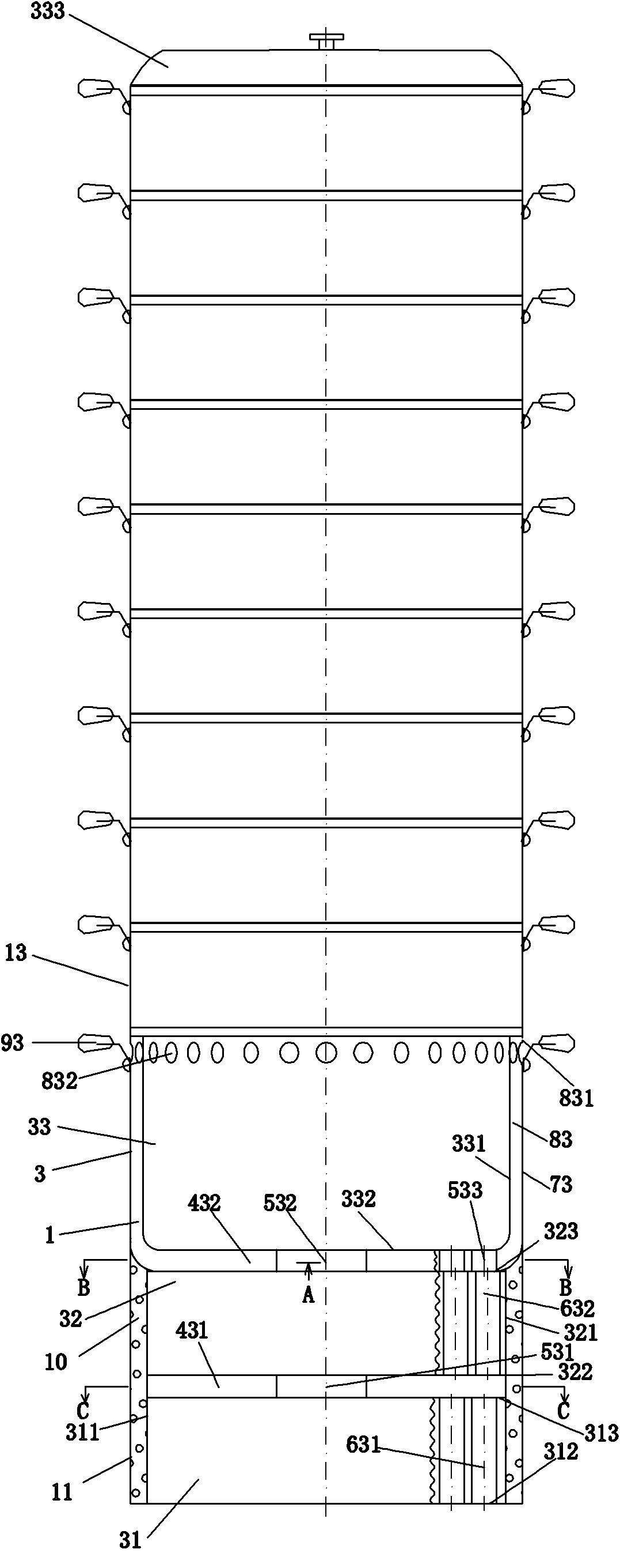
[0018] Embodiment 2, a three-stage energy-saving steamer. refer to Figure 3~Figure 6 , the pot body 1 of the three-stage energy-saving steamer is set into three-stage pot 3; the three-stage pot 3 is provided with a lower pot 31, a middle pot 32 and an upper pot 33, and the top surface 313 of the lower pot 31 and the bottom surface of the middle pot 32 322 are provided with a lower annular cavity 431 and a lower connecting pipe 531 along the central axis of the pot; an upper annular cavity 432 is provided between the top surface 323 of the middle pot 32 and the bottom surface 332 of the upper pot 33, and the middle pot 32 and the upper pot 33 along the central axis of the pot are provided with a central upper connecting pipe 532 and 16 upper connecting pipes 533 evenly distributed around the outermost circle of the central axis; Outer ring 73 with the same gap as shell 331, pot handle 93 is arranged on the upper part of outer ring 73, and outer ring 73 communicates with upper...

Embodiment 3

[0019] Embodiment 3, two-stage energy-saving stewing pot. refer to Figure 7 , compared with embodiment 1, the pot body 1 of the two-stage energy-saving stewing pot is correspondingly the same as in embodiment 1, and a stewing pot 14 and a pot cover 223 are arranged in the upper pot 22 to form a two-stage energy-saving stewing pot .


PUM


Abstract

The invention relates to an energy-saving boiler which comprises a boiler body, wherein the boiler body can be set into a two-section boiler or a three-section boiler. The two-section boiler consists of an upper-section boiler and a lower-section boiler, a plurality of siphon pipes are arranged in the lower-section boiler, a communicating pipe and an annular cavity are arranged between the upper-section boiler and the lower-section boiler, a smoke discharge channel provided with an equal-clearance external sleeve ring is arranged outside the upper-section boiler; the three-section boiler consists of a lower-section boiler, a middle-section boiler and an upper-section boiler, the lower-section boiler and the middle-section boiler are respectively provided with a plurality of lower siphon pipes and a plurality of upper siphon pipes, and a lower communicating pipe and a lower annular cavity are arranged between the lower-section boiler and the middle-section boiler; and an upper communicating pipe and an upper annular cavity are arranged between the middle-section boiler and the upper-section boiler, a smoke discharge channel provided with an equal-clearance external sleeve ring is arranged outside the upper-section boiler, and the lower siphon pipes and the upper siphon pipes are distributed in a staggered manner. A plurality of steamer grates or stewing and braising jacketed kettles are arranged on the upper-section boiler of the two-section boiler or the three-section boiler, thus forming an energy-saving steamer or an energy-saving stewing and braising boiler. The energy-saving boiler has the advantages of high heat exchange efficiency, environmental protection and energy conservation and the like.

Description

technical field [0001] The invention relates to an energy-saving pot, in particular to an energy-saving steamer and an energy-saving stewing pot. Background technique [0002] At present, domestic and foreign household steaming (stewing) pots have little difference in basic structure. Most of them are cylindrical pans with two or three steamer grates (or a set of stewing pots) and lids. The commercial specifications are larger. There are more grates in the steamer (or a larger pot for stewing and stewing), cylindrical or square, and the bottom of the pot is basically flat. Generally, steaming buns, steaming rice or stewing requires a long time to turn on the stove. , due to the flat bottom and small heating surface, only a part of the high-temperature flame flue gas heat flow of the stove exchanges heat with the water in the steamer, and most of the high-temperature flame flue gas heat flow overflows from the bottom of the pot due to the small heat transfer area and short he...

Claims


Application Information

Patent Timeline
Patent Type & Authority Applications(China)
IPC IPC(8): A47J27/04A47J27/13A47J27/16A47J27/00
Inventor 钟景武
Owner JIEYANG RENYUDE ENERGY SAVING TECH
Learn More