High-power LED illumination lamp metal radiator and manufacturing method

A technology of LED lighting lamps and metal heat sinks, applied in the field of lighting, can solve the problems of heavy weight, waste, large volume, etc., and achieve the effects of convenient application, reduction of consumption, and improvement of heat dissipation efficiency

Inactive Publication Date: 2011-07-20
TIANJIN ZHONGHUAN JINGRUI ELECTRONICS
View PDF4 Cites 6 Cited by
  • Summary
  • Abstract
  • Description
  • Claims
  • Application Information

AI Technical Summary

Problems solved by technology

However, the problem of heat dissipation of LED light sources is still prominent. The heat dissipation of medium and high-power LED lighting lamps mostly adopts integral cast aluminum heat sinks, which are large in size and heavy in weight.
Some LED lighting lamps design the radiator and lamps into one, for example: LED industrial and mining lamps design the radiator and lampshade as one, the radiator of LED street lamps is the lampshade, etc., the original lighting should be replaced with LED lighting It is necessary to replace the lamps as a whole, and some even have to change the original decoration, causing unnecessary waste and trouble

Method used


Image

  • High-power LED illumination lamp metal radiator and manufacturing method
  • High-power LED illumination lamp metal radiator and manufacturing method
  • High-power LED illumination lamp metal radiator and manufacturing method

Examples


Embodiment Construction

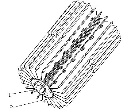
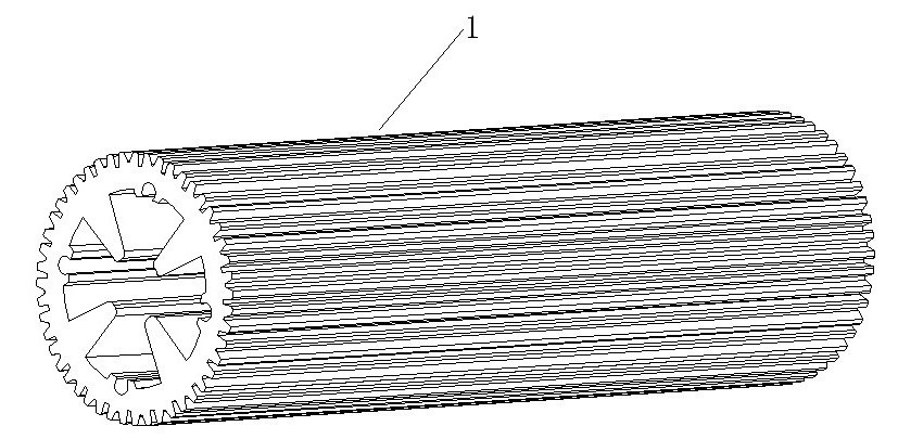
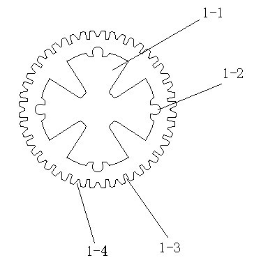
[0024] Such as Figure 1 to Figure 4 As shown, a metal radiator of a high-power LED lighting lamp includes a cooling shaft 1 and a cooling fin 2. The cooling shaft 1 is a cylinder, and a through hole 1-1 is provided at the center of the cylinder. The end surface is correspondingly provided with positioning holes 1-2 connected at both ends, and several U-shaped insert grooves 1-3 and an equal number of V-shaped sheet-pressing grooves 1-4 are uniformly arranged on the circumferential surface of the heat dissipation shaft 1. Shape insert groove 1-3 and V-shaped sheet pressing groove 1-4 are arranged at intervals; Heat sink 2 is a rectangular sheet shape, and its upper end two angles are symmetrical arc angles 2-1, set on the face of heat sink 2 There are several rectangular reinforcing grooves 2-2 and several heat dissipation holes 2-3; the lower ends of several heat dissipation fins 2 are squeezed into several U-shaped insert grooves 1-3 on the heat dissipation shaft 1 respectiv...


PUM


Abstract

The invention relates to a high-power light emitting diode (LED) illumination lamp metal radiator and a manufacturing method. The radiator comprises a radiating shaft and radiating fins, wherein the radiating shaft is of a cylinder, the circle center of the cylinder is provided with a through hole, two end faces of the radiating shaft are correspondingly provided with positioning holes communicated at two ends, the circumferential surface of the radiating shaft is uniformly provided with a plurality of U-shaped insert slots and V-shaped pressing plate slots in the same number as the U-shaped insert slots, and the U-shaped insert slots and the V-shaped pressing plate slots are formed at intervals; the radiating fins are rectangular sheets, two angles at the upper ends of the radiating fins are symmetrical arc angles, and the surfaces of the radiating fins are provided with a plurality of rectangular reinforcing slots and a plurality of radiating holes; and the right-angled sides of a plurality of radiating fins are extruded into the plurality of U-shaped insert slots on the radiating shaft respectively. The radiator has the advantages that the radiating efficiency is improved, the weight and the volume are reduced and the consumption of raw materials is reduced. The radiator can directly replace the conventional incandescent lamp or energy-saving lamp, so the application range of the radiator is enlarged, the application of an LED illumination lamp is more convenient and the application range is wider.

Description

technical field [0001] The invention relates to the field of lighting, in particular to a metal radiator of a high-power LED lighting lamp and a manufacturing method thereof. Background technique [0002] At present, the development speed of LED lighting in my country is very fast, and the integration of luminous body chips is getting higher and higher, and the single chip has reached the level of high power. However, the problem of heat dissipation of LED light sources is still prominent. The heat dissipation of medium and high-power LED lighting lamps mostly adopts integral cast aluminum heat sinks, which are large in size and heavy in weight. Some LED lighting lamps design the radiator and lamps into one, for example: LED industrial and mining lamps design the radiator and lampshade as one, the radiator of LED street lamps is the lampshade, etc., the original lighting should be replaced with LED lighting It is necessary to replace the lamps as a whole, and some even chan...

Claims


Application Information

Patent Timeline
IPC IPC(8): F21V29/00F21Y101/02F21V29/77F21V29/83F21V29/89F21Y115/10
Inventor 李春峰陈德忠王国华许岩杨学斌王斌邰书勇杨晓娟
Owner TIANJIN ZHONGHUAN JINGRUI ELECTRONICS
Why Eureka
Try Eureka