
Energy storage bidirectional current converter for high-capacity storage battery

A technology of bidirectional converters and batteries, which is applied in current collectors, battery circuit devices, electric vehicles, etc., can solve problems such as switching loss, increased design complexity, system withdrawal, and reduced system reliability, and achieves convenient expansion and maintenance. The effect of protecting safety and ensuring utilization

Inactive Publication Date: 2011-07-13
POWER GRID TECH RES CENT CHINA SOUTHERN POWER GRID +2
View PDF3 Cites 53 Cited by
  • Summary
  • Abstract
  • Description
  • Claims
  • Application Information

AI Technical Summary

Problems solved by technology

The advantages of the single-stage structure are simple structure, small size, high system efficiency and reliability; the disadvantage is the input of a single battery pack, and the lack of optimal design for the battery pack technical requirements of large-capacity energy storage power stations
The advantages of the two-stage structure Wide DC voltage range input, no step-up transformer, the disadvantage is that the switching loss and design complexity of the front-end DC / DC link are increased, and it is still a single input, which lacks the reliability, life, and reliability of the battery pack. Optimized design for maintenance etc.
[0005] At present, the large-capacity battery grouping scheme mostly adopts the high-power centralized access method, which requires a large number of battery packs to be connected in parallel on the DC side. This large-capacity direct parallel connection method not only produces circulation problems, but also damages one single cell. Exit, making the system reliability greatly reduced

Method used


Image

  • Energy storage bidirectional current converter for high-capacity storage battery
  • Energy storage bidirectional current converter for high-capacity storage battery
  • Energy storage bidirectional current converter for high-capacity storage battery

Examples


Embodiment Construction

[0019] The technical solution of the present invention will be further described in detail below according to the drawings in the description and in combination with specific implementation examples.

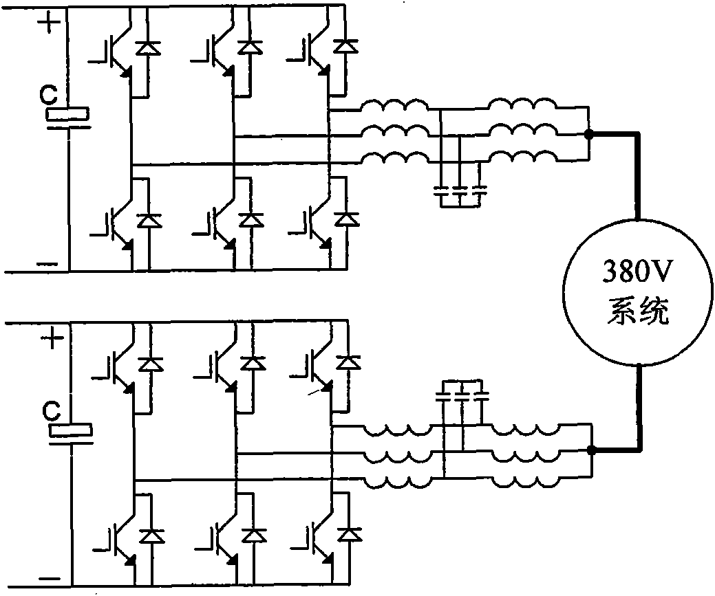
[0020] figure 1 Shown is a schematic diagram of the main circuit of the energy storage bidirectional converter, which adopts a DC / DC+DC / AC dual-stage structure. The battery pack is divided into N groups according to the capacity and connected to the front-stage DC / DC. The DC / DC module unit is connected to an independent DC bus and connected to the corresponding DC / AC converter to realize energy exchange with the grid or independent load operation.

[0021] figure 2 The structure diagram of the DC / DC module unit is shown. A battery pack can be connected to the left and right sides of the DC / DC power module. Each module is composed of two back-to-back three-arm modules. The upper and lower bridge arms of the three-arm unit The midpoints are connected together via a reactor and ...


PUM


Abstract

The invention discloses a design scheme of an energy storage bidirectional current converter for a high-capacity storage battery. The current converter utilizes a modularization design idea and supports the idea that a plurality of branch DC / DC modules are connected in parallel and then are connected to a DC bus bar. The problems of circulation and current sharing caused by serial and parallel connection of battery packs are solved. Energy collected by the DC bus bar is exchanged with the energy of a power grid or an independent load through a backward DC / AC current converter. Due to the adoption of a technology of time-sharing rotation and dynamic hibernation, the efficiency of a system under the low power and electric energy quality at the AC and DC sides can be effectively improved so as to realize balanced use of the battery packs. Each storage battery branch is subjected to automatic and intelligent charge and discharge management, a control function and a protection function are completely independently configurated, and the highest availability of the system is ensured. An experimental result shows that the energy storage bidirectional current converter for the high-capacity storage battery has good universality, practicality and application prospect.

Description

technical field [0001] The invention belongs to the technical field of battery energy storage in the field of smart grids, and is suitable for the design of large-capacity energy storage bidirectional converters. Background technique [0002] With the development of intelligent control technology, developed industrial countries have taken the construction of smart grid as an important strategic measure to seize the commanding heights of the future low-carbon economy. As a key link in the smart grid, energy storage technology has a broad application prospect in the power system due to its functions of peak shaving and valley filling and stable access to new energy. The battery energy storage system is mainly composed of four parts: battery, energy conversion system, battery management system and monitoring system. The energy conversion system (Power Conversion System, PCS) is the core equipment of the energy storage power station. At present, large-capacity battery energy st...

Claims


Application Information

Patent Timeline
IPC IPC(8): H02J3/32H02J7/00
CPCY02E70/40Y02B40/90Y02E60/10
Inventor 陆志刚董旭柱李战鹰黄晓东刘志超周志超刘树操丰梅梅红明石山刘浩王皆庆赵璐璐
Owner POWER GRID TECH RES CENT CHINA SOUTHERN POWER GRID
Learn More