Method and device for controlling fault tolerance of battery management system of electric automobile
A battery management system, fault-tolerant control technology, applied in the direction of electric vehicle charging technology, electric vehicles, circuits or fluid pipelines, etc., can solve problems such as power battery failure, powerlessness, etc., to reduce accidents, ensure life and property safety, improve The effect of driving safety
- Summary
- Abstract
- Description
- Claims
- Application Information
AI Technical Summary
Problems solved by technology
Method used
Image

Examples
Embodiment 1
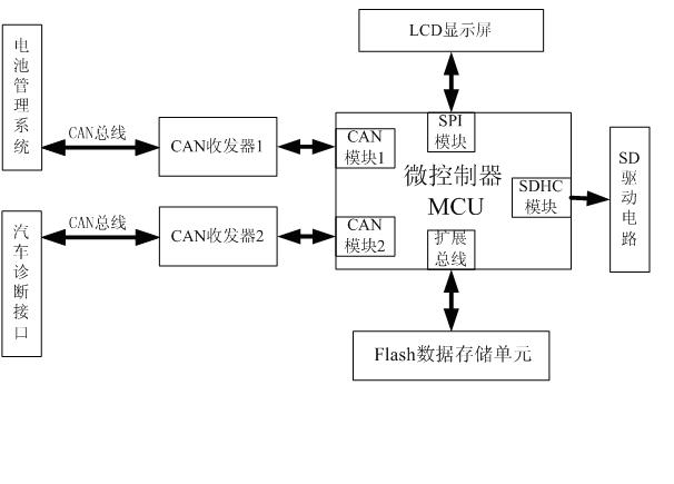
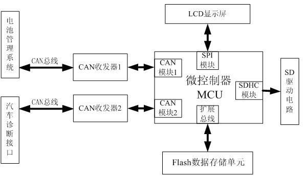
[0029] The fault-tolerant control device is mainly composed of MCU, CAN transceiver, FLASH data storage unit, LCD display and SD card drive circuit. Among them, the CAN communication module of the MCU is connected to the CAN bus interface of the BMS after the level conversion of the CAN transceiver, reads the fault code of the BMS, parses out the fault information of the current BMS, writes it into the FLASH data storage unit for backup, and saves the information Displayed on the LCD display for the driver to view. At the same time, the fault-tolerant control device will select a corresponding fault-tolerant control strategy based on the fault information, and the CAN communication module will send fault-tolerant control commands to the BMS. BMS executes fault-tolerant processing actions according to this command.
[0030] The other CAN communication module of the fault-tolerant control device MCU is connected to the vehicle diagnostic interface after level conversion by the ...
Embodiment 2
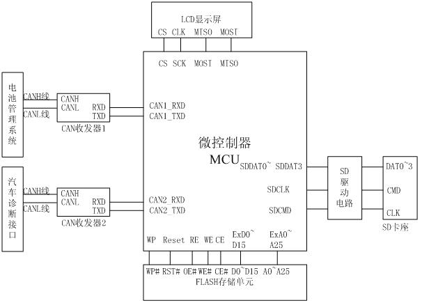
[0032] Such as figure 2 As shown: the signal receiving pin CAN1_RXD and the signal transmitting pin CAN1_TXD of the CAN communication module 1 of the MCU are connected with the signal receiving pin RXD and the signal transmitting pin TXD of the CAN transceiver 1 to complete the TTL level transmission of the CAN bus; The CANH1 terminal and the CANL1 terminal of the CAN transceiver 1 are connected to the CAN bus interface CANH terminal and the CANL terminal of the BMS to complete the differential level transmission of the CAN bus, thus realizing the conversion between the TTL level and the differential level.
[0033] The reading and writing of the FLASH data storage unit adopts the way of the extended bus, and its write protection line WP#, reset line RST#, read enable line OE#, write enable line WE#, and chip select line CE# are respectively connected with the MCU’s The expansion bus pin connection completes the data storage function of FLASH. Among them, the FLASH data inpu...
PUM
 Abstract
Description
Claims
Application Information
 - R&D
- Intellectual Property
- Life Sciences
- Materials
- Tech Scout
- Unparalleled Data Quality
- Higher Quality Content
- 60% Fewer Hallucinations
Browse by: Latest US Patents, China's latest patents, Technical Efficacy Thesaurus, Application Domain, Technology Topic, Popular Technical Reports.
© 2025 PatSnap. All rights reserved.Legal|Privacy policy|Modern Slavery Act Transparency Statement|Sitemap|About US| Contact US: help@patsnap.com