Signal reception device and signal transmission system

A signal receiving device and signal transmission technology, applied in transmission systems, digital transmission systems, synchronization devices, etc., can solve problems such as performance degradation, system structure limitations, and sound quality degradation

Inactive Publication Date: 2011-06-29
MITSUBISHI ELECTRIC CORP
View PDF1 Cites 8 Cited by
  • Summary
  • Abstract
  • Description
  • Claims
  • Application Information

AI Technical Summary

Problems solved by technology

[0011] However, according to Figure 5 The conventional PLL method shown requires simultaneous tracking of the center frequency and removal of jitter components, so there is a limit to removing jitter of low frequency band components near the center frequency inherent in the clock, since the tracking performance is degraded. It becomes the main cause of performance deterioration and sound quality deterioration of SN ratio (Signal to Noise Ratio: Signal to Noise Ratio)
Additionally, according to Image 6 In the SRC method shown, although the reference clock generation circuit 203 of the D / A circuit 202 can be reduced to crystal precision, the jitter component contained in the transmission system cannot be separated from the signal component, which is compared with the above-mentioned PLL method not much difference
[0012] in addition, Figure 7 In the shown dual link method, although both the jitter related to the transmission system and the jitter of the reference clock of the D / A circuit 202 can be reduced to crystal precision in terms of performance, the signal transmission device 10 needs to communicate with the external clock correspond
Therefore, in the case of a plurality of playback sources, signal transmission paths 30, 50 corresponding to the number are required, and there is a limitation on the system structure.
[0013] Moreover, according to Figure 8 The large-capacity buffering method shown will cause a time delay, so for example, as a certain playback time passes, the time deviation will gradually increase between the digital input signal and the analog output signal. Real-time audio-video playback that synchronizes audio and video
[0014] In addition, according to the technology disclosed in the above-mentioned Patent Document 1, the image data corresponding to the size of the noise extracted per unit time is randomly dispersed so that there is no visual problem, but when it is used for audio and video playback , will cause deterioration of sound quality

Method used


Image

  • Signal reception device and signal transmission system
  • Signal reception device and signal transmission system
  • Signal reception device and signal transmission system

Examples


Embodiment approach 1

[0029] [Explanation of the signal transmission system]

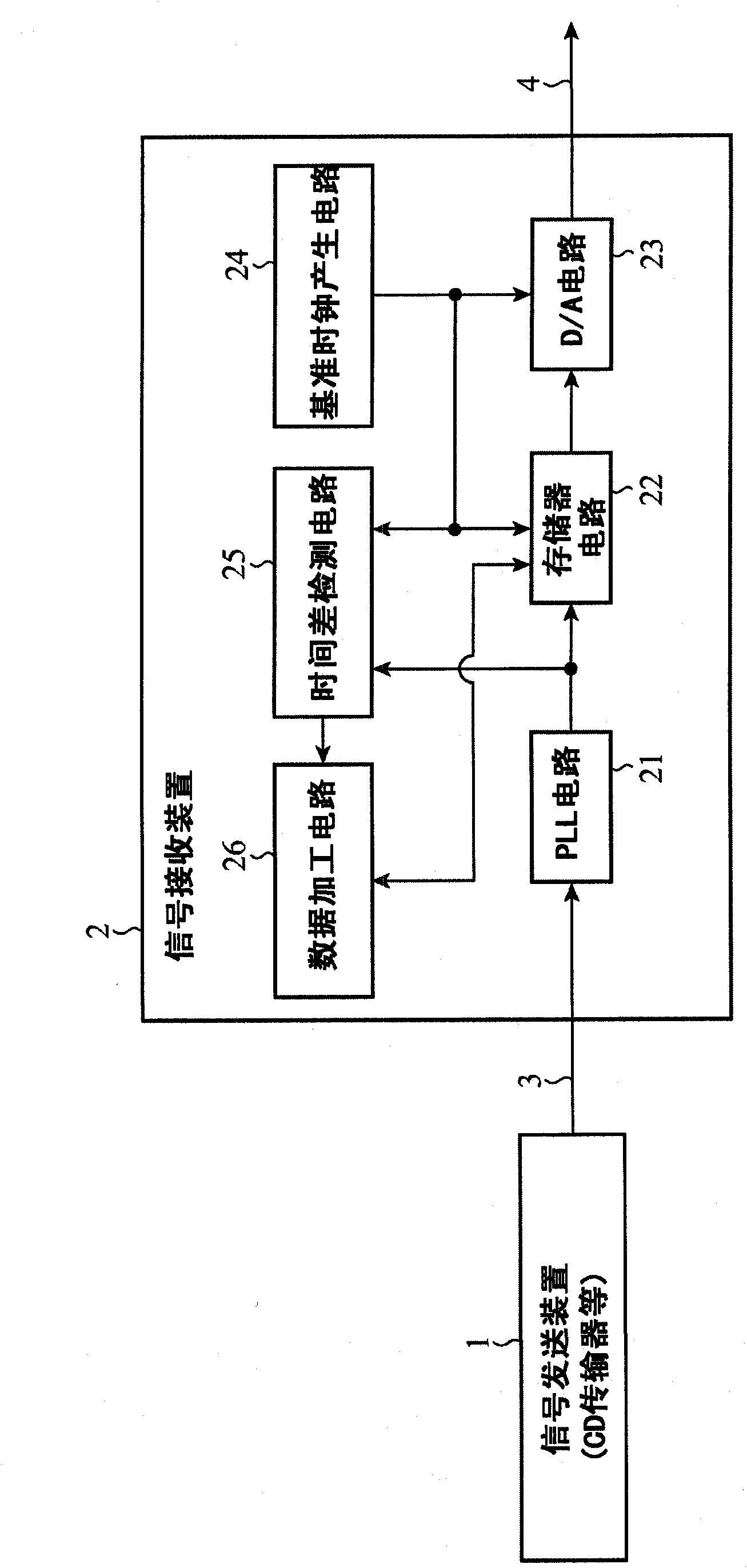
[0030] figure 1 It is a block diagram showing the configuration of the signal transmission system according to Embodiment 1 of the present invention.

[0031] Such as figure 1 As shown, the signal transmission and reception system according to Embodiment 1 of the present invention includes a signal transmission device 1 and a signal reception device 2 connected to the signal transmission device 1 through a signal transmission line 3 . In addition, the signal transmission path 3 may be either wired or wireless.

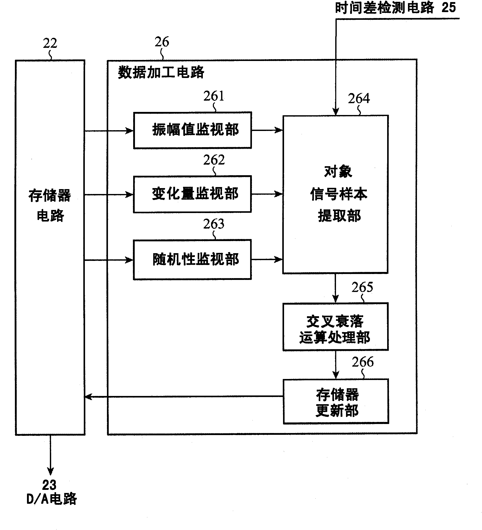
[0032] Such as figure 1 As shown, the signal receiving device 2 includes a PLL circuit 21 , a memory circuit 22 , a D / A circuit 23 , a reference clock generation circuit 24 (clock B), a time difference detection circuit 25 , and a data processing circuit 26 .

[0033] The PLL circuit 21 separates and generates a clock A from the digital input signal transmitted from the signal transmission device 1 via the...


PUM


Abstract

A signal reception device (2) includes a memory circuit (22). Data contained in a digital input signal transmitted from a signal transmission device (1) is written by using a clock separated / generated from the received digital input signal by using a PLL circuit (21) and read by using a reference clock of crystal accuracy from a reference clock generation circuit (24). Here, a difference between the clock and the reference clock is detected so as to correct the difference to reproduce the digital input signal. If the signal reception device (2) delays as compared to the signal transmission device (1), the data contained in the digital input signal is thinned. If the signal reception device (2) advances as compared to the signal transmission device (1), a signal generated from the preceding and the following digital input signals is interpolated.

Description

technical field [0001] The present invention relates to a signal receiving device and a signal transmission system suitable for example for asynchronous digital transmission between a CD transmitter and a D / A converter. Background technique [0002] In the field of asynchronous digital transmission, for example, in CD (Compact Disc: Compact Disc) playback, signal transmission devices such as CD transmitters and built-in D / A (Digital / Analog: Digital / Analog) converters Digital signals are transmitted asynchronously between signal receiving devices. [0003] At this time, in order to perform high-quality reproduction, it is necessary to absorb the deviation (time difference) of the clocks used in the signal transmitting device and the signal receiving device respectively. [0004] Conventionally, various control methods have been proposed for this purpose. For example, if Figure 5 As shown, a PLL method is generally known: that is, a PLL (Phase Locked Loop: Phase Locked Loop...

Claims


Application Information

Patent Timeline
Patent Type & Authority Applications(China)
IPC IPC(8): G10L19/00G11B20/10H04L7/00H04N5/95
CPCG11B27/038G11B20/225G11B20/10379H04N21/44004H04N21/23406G11B20/10037H04N9/896G11B20/1024H04N21/42646G11B20/10009G11B20/10398G11B20/10222H04N21/4305G11B2220/2545
Inventor 寺本浩平木村胜仲田刚齐藤文训
Owner MITSUBISHI ELECTRIC CORP
Why Eureka
Try Eureka