
Ultra broadband antenna of integrated filter

An ultra-wideband antenna and filter technology, applied in the direction of antenna, antenna array, radiating element structure, etc., can solve the problems of mismatch between antenna and microwave circuit, complex antenna structure and process, reducing the overall efficiency of the system, etc., to achieve good filtering features, ease of integration, and reduced complexity

Inactive Publication Date: 2011-06-29
HARBIN ENG UNIV
View PDF4 Cites 20 Cited by
  • Summary
  • Abstract
  • Description
  • Claims
  • Application Information

AI Technical Summary

Problems solved by technology

Usually, this method will cause mismatch between the antenna and the microwave circuit, and even reduce the overall performance of the system, and it is difficult to realize the miniaturization of the equipment. Therefore, the ultra-wideband antenna with integrated filter structure is one of the important methods to solve this problem.
At the same time, there are some shortcomings in the existing antennas that solve this problem: (1) the structure and process of the currently designed antennas are relatively complicated, so designing an antenna with a simple structure has become a research focus at this stage
(2) At present, most ultra-wideband antennas usually need to drill holes during system integration, and use reactive elements to connect to the RF front-end, so the complexity of the system is increased, the performance of the system is reduced, and the needs of miniaturization cannot be met.
However, it still cannot overcome the current electromagnetic interference problem
The document "Harmonic Control For An Integrated Microstrip Antenna With Loaded Transmission Line, Shun-Yun Lin, Kuang-Chih Huang, and Jin-Sen Chen. Microwave And Optical Technology Letters, Vol.44, No.4, February, 2005", proposed One uses periodic structure to suppress harmonics, but it is large in size and complex in structure
In order to overcome the above shortcomings, the document "Design of a 5.8-GHz Rectenna Incorporating a New Patch Antenna, Ching-Hong K.Chin, Quan Xue, Chi Hou Chan, IEEE Antennas And Wireless Propagation Letters, Vol.4, 2005", elaborated The method of etching the filter on the coplanar waveguide feeder to achieve the characteristics of the notch, but the volume is still large
Literature "A miniaturized monopole antenna for ultra-wide band applications with band-notch Filter, B. Ahmadi, R. Faraji-Dana, IET Microw. Antennas Propag., 2009, Vol.3, Iss.8, pp.1224 1231." Describes the ultra-wideband antenna with notch characteristics etched U-shaped groove and V-shaped groove, but the volume is large, and the gradient feed structure is used, resulting in complex structure and difficult design and debugging

Method used


Image

  • Ultra broadband antenna of integrated filter
  • Ultra broadband antenna of integrated filter
  • Ultra broadband antenna of integrated filter

Examples


Embodiment 1

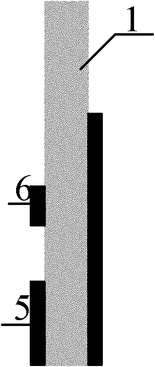
[0021] Example 1 of the present invention such as figure 1 , figure 2 and image 3 shown. It consists of a dielectric substrate 1 , a radiation unit 2 , a split resonant ring 3 etched on the radiation unit, a microstrip feed structure 4 , and partial ground structures 5 and 6 . The microstrip feeding structure of the antenna is realized by a section of 50Ω microstrip line, one section is directly connected to the radiation unit, and the other section is connected to the SMA inner conductor. The outer conductor of the SMA is connected to the part printed on the backside. according to figure 1 , 2 , The antenna structure shown in 3, as long as the appropriate size is selected and the size of the split resonator ring is properly designed according to the split resonator ring theory, the communication between UWB communication and existing narrowband systems can be realized, such as UWB communication and WLAN Electromagnetic compatibility of ultra-wideband communication and...

Embodiment 2

[0023] Embodiment 2 of the present invention is as Figure 4 , Figure 5 , Image 6 As shown, it consists of a dielectric substrate 1 , a radiation unit 2 , a split resonator ring 3 etched on the radiation unit, a microstrip feed structure 4 , and a partial ground structure 5 . The microstrip feeding structure of the antenna is realized by a section of 50Ω microstrip line, one section is directly connected to the radiation unit, and the other section is connected to the SMA inner conductor. The outer conductor of the SMA is connected to the part printed on the backside. according to Figure 4 , 5 For the antenna structure shown in , 6, as long as the appropriate size is selected and the size of the split resonator ring is properly designed according to the split resonator ring theory, the communication between UWB communication and existing narrowband systems can be realized, such as UWB communication and WLAN Electromagnetic compatibility of ultra-wideband communication ...


PUM


Abstract

The invention provides an ultra broadband antenna of an integrated filter, which comprises a medium substrate, a microstrip feeder structure of a radiating unit arranged on one side of the medium substrate, the other side of the medium substrate is partially grounded, the radiating unit is provided with a split-ring resonator (SRR), and a microstrip line is directly connected to the radiating unit. The antenna relates to the invention has excellent broadband property and good omnidirectional radiation property, and the antenna is integrated with a filter with a complementary split-ring resonator (CSRR), so that the influence between the communication of local area network and ultra broadband communication system of the antenna can be prevented. The antenna provided by the invention has the advantages that the design is simple and compact, the volume is small, the process is convenient and the cost is low. The antenna can be applied to electronic reconnaissance device and electronic countermeasure device and the like.

Description

technical field [0001] The invention relates to an ultra-wideband antenna with integrated filter, which can be used for receiving and transmitting radio waves. In civil use, it can be used as a terminal receiving device for ultra-wideband wireless communication. Background technique [0002] Since radio communication equipment and electronic information equipment are developing toward multi-functionality, miniaturization, ultra-wideband, and friendly coordination with the surrounding environment, this makes broadband, miniaturization, and high gain one of the hot research topics at home and abroad. In recent years, microstrip antenna technology has developed rapidly, and the structure can be fabricated by photographic technology and has good polarization characteristics. Therefore, this technology has been applied in the design of ultra-wideband antennas and related microwave circuit components. However, the frequency band occupied by the current ultra-wideband communicatio...

Claims


Application Information

Patent Timeline
IPC IPC(8): H01Q21/00H01Q1/36
Inventor 周旺姜弢李迎松刘乘源
Owner HARBIN ENG UNIV
Learn More