Liquid crystal display

A liquid crystal display and liquid crystal panel technology, applied in static indicators, instruments, nonlinear optics, etc., can solve the problems of light leakage, limited area, long distance, etc., and achieve the effect of solving light leakage

Inactive Publication Date: 2011-06-29
AU OPTRONICS CORP
View PDF5 Cites 20 Cited by
  • Summary
  • Abstract
  • Description
  • Claims
  • Application Information

AI Technical Summary

Problems solved by technology

However, due to the limited area of ​​the black matrix layer and the long distance from the light source, some large-angle light will pass through the LCD panel and enter the human eye, resulting in light leakage.

Method used


Image

  • Liquid crystal display
  • Liquid crystal display
  • Liquid crystal display

Examples


Embodiment Construction

[0034] A number of embodiments of the present invention will be disclosed in the following figures. For the sake of clarity, many practical details will be described together in the following description. It should be understood, however, that these practical details should not be used to limit the invention. That is, in some embodiments of the present invention, these practical details are unnecessary. In addition, for the sake of simplifying the drawings, some well-known and commonly used structures and elements will be shown in a simple schematic manner in the drawings.

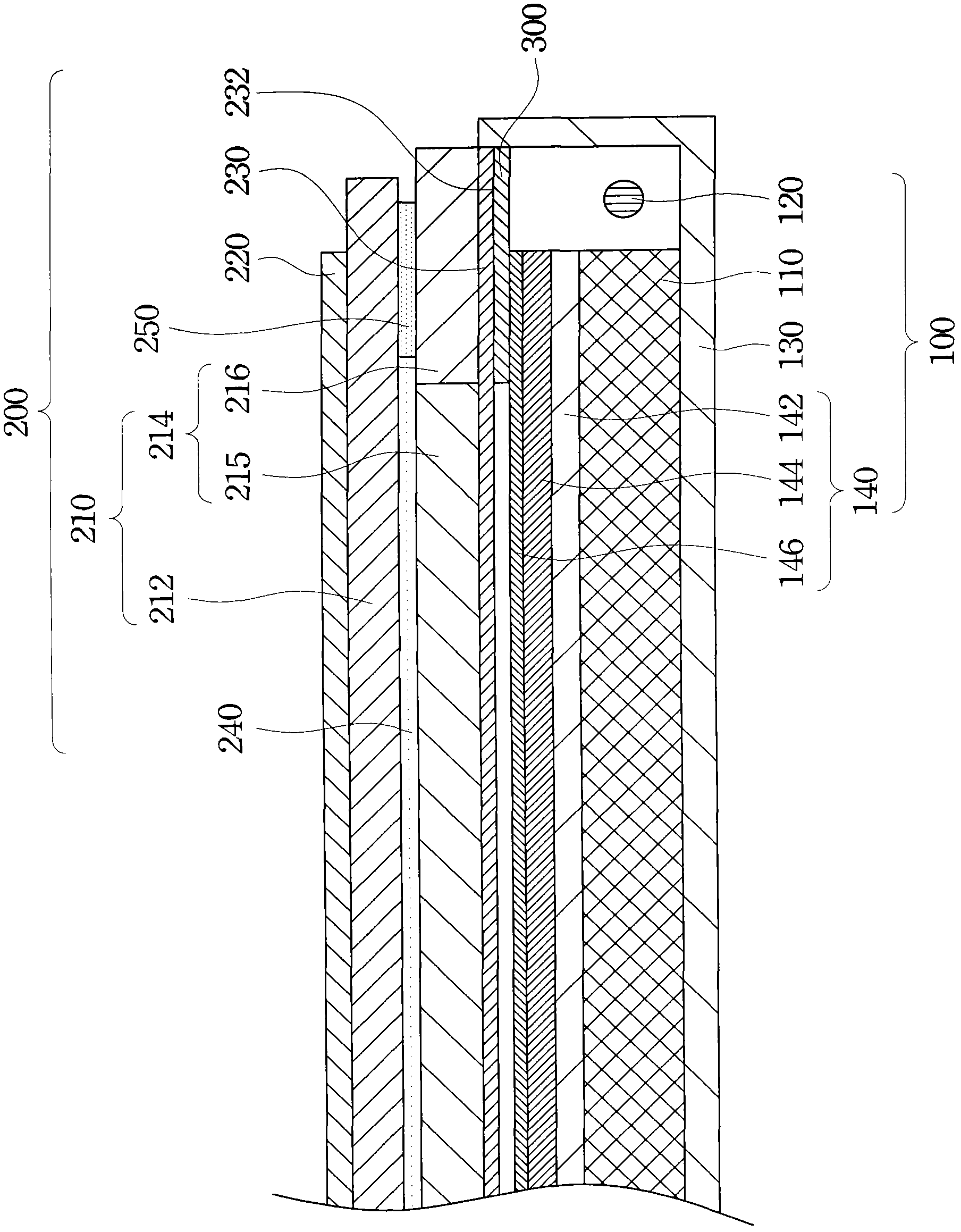
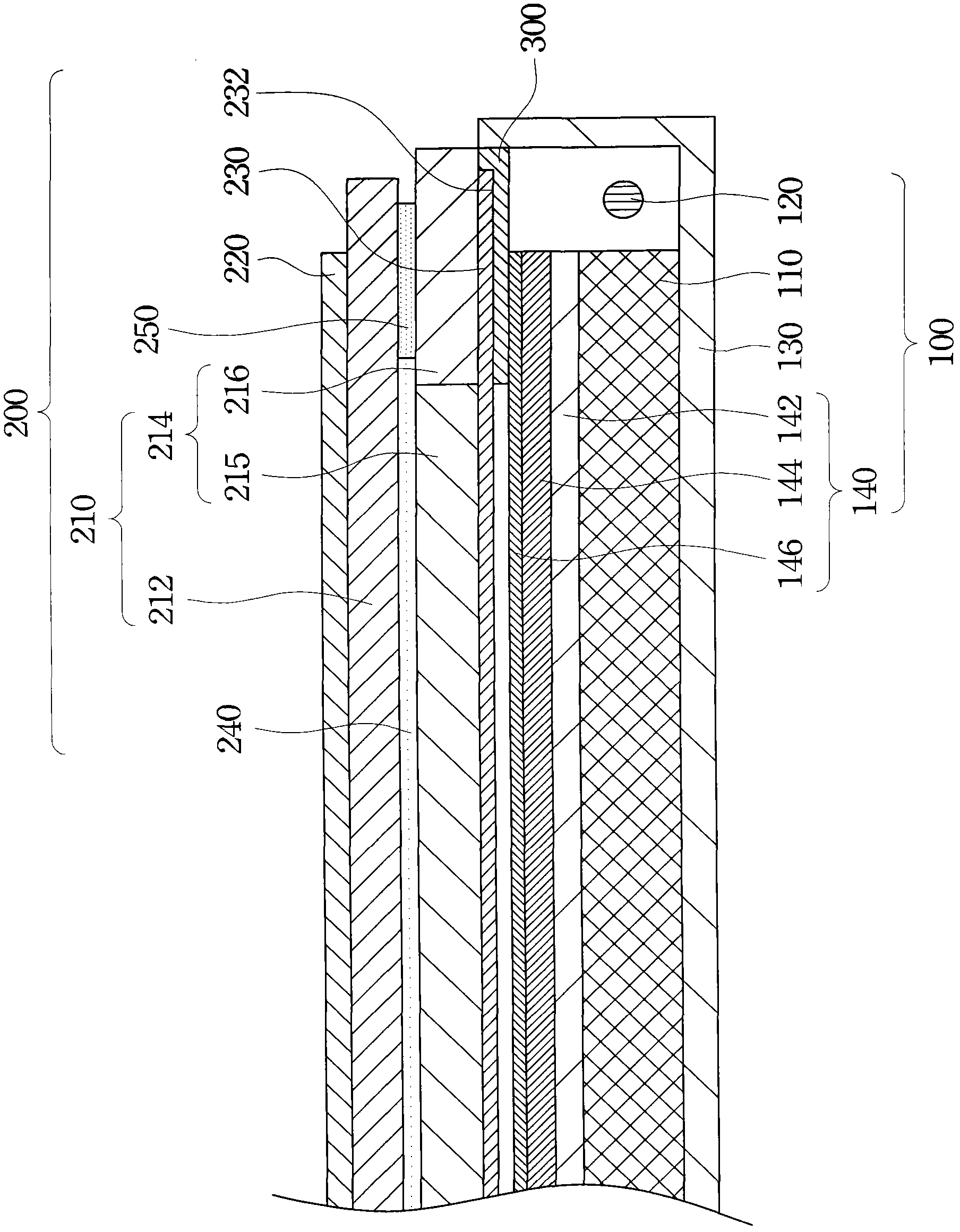
[0035] figure 1 is a cross-sectional view of a liquid crystal display according to an embodiment of the present invention. As shown in the figure, a liquid crystal display includes a backlight module 100 , a liquid crystal panel 200 and a light shielding layer 300 . The liquid crystal panel 200 is disposed on the light emitting side of the backlight module 100 , and the liquid crystal panel 200 includes...


PUM


Abstract

A liquid crystal display comprises a backlight module, a liquid crystal panel, and a light-shield layer. The liquid crystal panel is disposed at the light extraction side of the backlight module, and the liquid crystal panel comprises a first polarizer, a pair of substrates, a liquid crystal layer, and a second polarizer. The pair of the substrates are disposed between the first polarizer and the backlight module. The liquid crystal layer is disposed between the pair of the substrates. The second polarizer is disposed between the substrate and the backlight module, and the second polarizer comprises a first surface facing the backlight module. The light-shield layer is disposed on the first surface.

Description

technical field [0001] The invention relates to a liquid crystal display. Background technique [0002] At present, there are many application markets for liquid crystal displays, including communications, handheld mobile devices, automotive liquid crystal display screens, monitors, notebook computers and personal computers, and will replace traditional cathode ray tubes (Cathode Ray Tubes) ; CRT) screen. [0003] At present, most liquid crystal displays set a black matrix layer in the liquid crystal panel to prevent the light emitted by the backlight module from leaking from the edge. However, due to the limited area of ​​the black matrix layer and the long distance from the light source, some large-angle light will pass through the liquid crystal panel and enter human eyes, resulting in light leakage. Especially for the liquid crystal display used in notebook computers, since the light emitted by the light source will pass through the reflection of the side wall and exce...

Claims


Application Information

Patent Timeline
Patent Type & Authority Applications(China)
IPC IPC(8): G02F1/1335G02F1/13357G02F1/133
Inventor 彭赐光罗德亨赵浩良
Owner AU OPTRONICS CORP
Why Eureka
Try Eureka