High-power LED bulb
A LED light bulb, high-power technology, applied in the direction of lamp shades, cooling/heating devices of lighting devices, lighting and heating equipment, etc., can solve the problems of low efficiency, discounted energy saving effect, short service life, etc., to increase the heat dissipation area and avoid Electric shock, safety improvement effect
- Summary
- Abstract
- Description
- Claims
- Application Information
AI Technical Summary
Problems solved by technology
Method used
Image
Examples
Embodiment 1
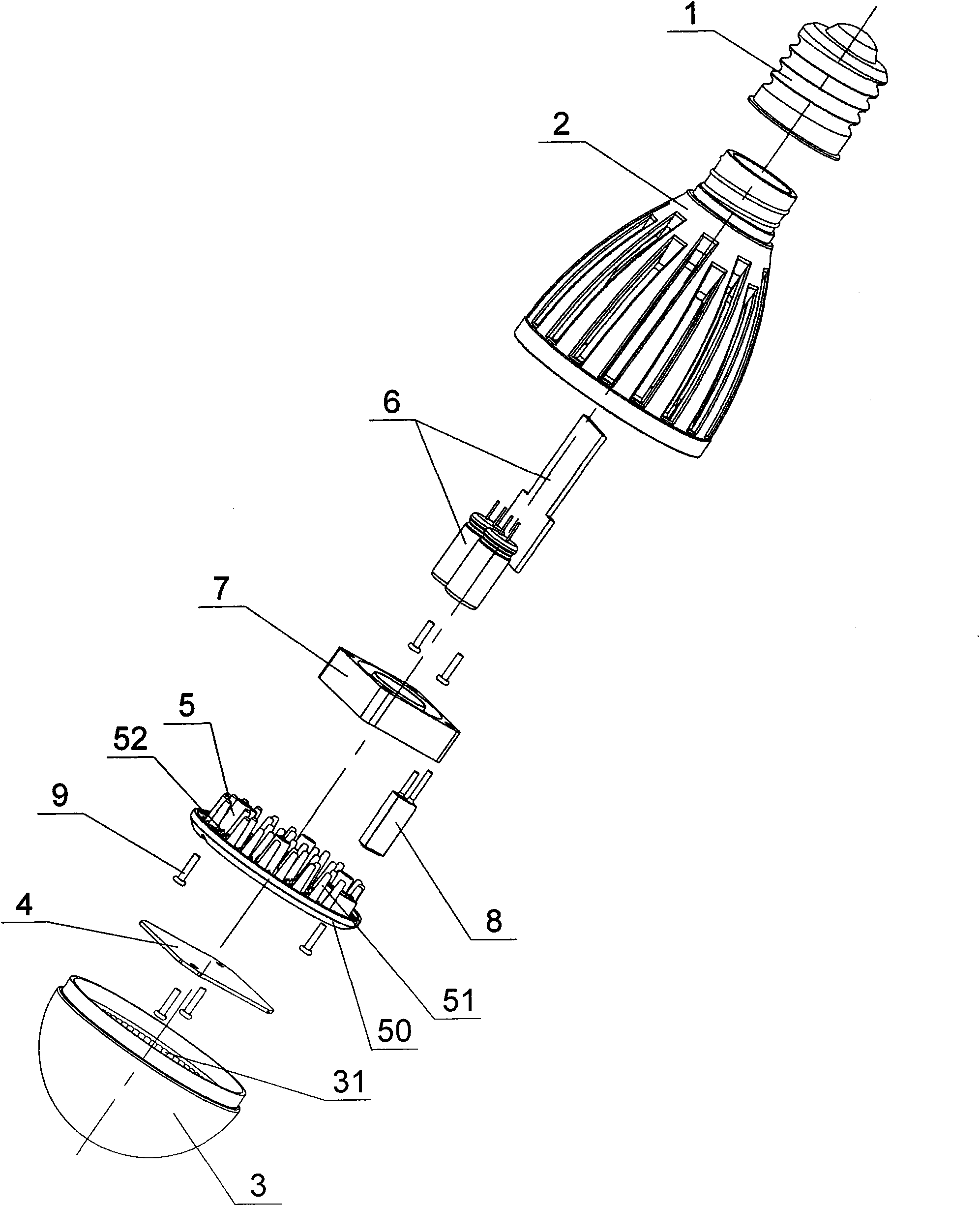
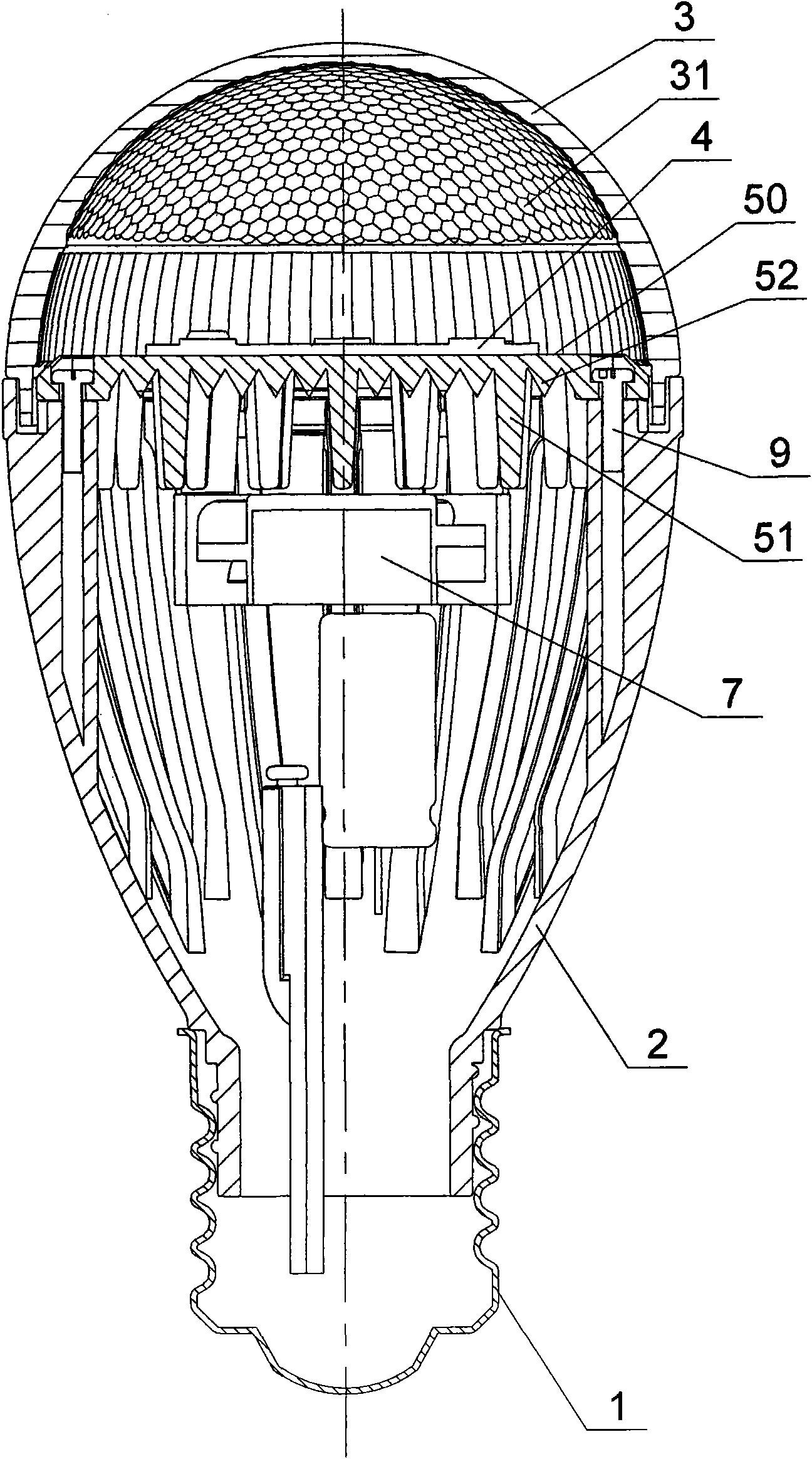
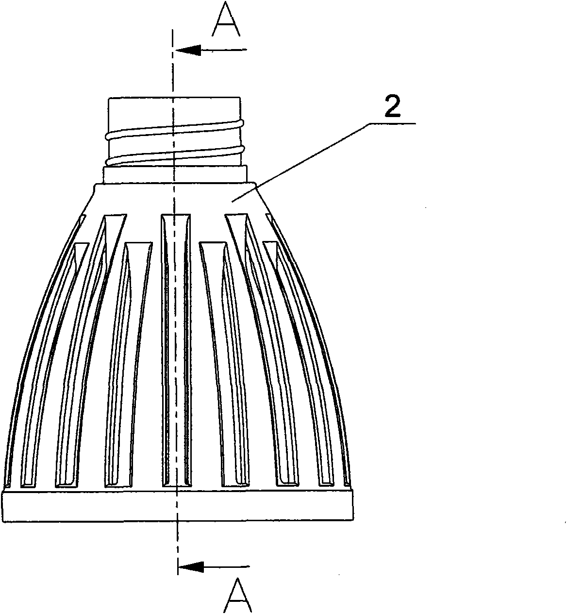
[0024] Such as Figure 1 ~ Figure 4 As shown, the LED light bulb of this embodiment includes a lamp cap 1, an insulating housing 2 with an inner cavity, an insulating light-transmitting front lampshade 3, a light source board 4 integrating LED chips, a radiator 5, a driving power supply assembly 6, and a cooling fan 7 . A thermosensitive switch 8 for cutting off the power supply when the lamp is at high temperature. The front end of the insulating housing 2 is fixedly connected with the insulating light-transmitting front lampshade 3 to form an accommodating cavity. The light source board 4, the The radiator 5, the driving power supply assembly 6, the heat dissipation fan 7, and the thermal switch 8 are all placed in the accommodating cavity, and the rear end of the insulating shell 2 is fixed to the lamp cap 1. connected, the inner wall of the insulated light-transmitting front lampshade 3 is provided with a light distribution pattern 31 to improve the light distribution effe...
Embodiment 2
[0028] Such as Figure 5 , Figure 6 , Figure 8 As shown, the difference between this embodiment and Embodiment 1 is: in this embodiment, no shielding portion 22 is provided in the side wall of the insulating housing 2, so as to increase the speed of heat flow and reduce the path of heat flow; In addition, the drive control circuit of this embodiment includes two loads connected in series with several LEDs, each load is connected in series with a constant current control circuit composed of a constant current source MOS device CCS, and after the series connection, the two loads are connected in parallel to the circuit , the loads controlled by the two roads can not interfere with each other. After one road is damaged, the other road can still work.
[0029] The remaining features of this embodiment are the same as those of Embodiment 1.
Embodiment 3
[0031] Such as Figure 9 As shown, the difference between this embodiment and Embodiment 1 is that in this embodiment, no heat dissipation fan 7 is provided, and the heat is directly dissipated to the outside through the heat dissipation groove 21 through the natural convection of heat; correspondingly, this embodiment The drive control circuit of the embodiment also does not include a fan circuit. This embodiment is suitable for use when the power is relatively small, but it can still ensure normal operation at a power of 1-4W.
[0032] The remaining features of this embodiment are the same as those of Embodiment 1.
PUM
 Abstract
Description
Claims
Application Information
 - R&D
- Intellectual Property
- Life Sciences
- Materials
- Tech Scout
- Unparalleled Data Quality
- Higher Quality Content
- 60% Fewer Hallucinations
Browse by: Latest US Patents, China's latest patents, Technical Efficacy Thesaurus, Application Domain, Technology Topic, Popular Technical Reports.
© 2025 PatSnap. All rights reserved.Legal|Privacy policy|Modern Slavery Act Transparency Statement|Sitemap|About US| Contact US: help@patsnap.com


