
Wind-speed and rotating-speed sensorless full-wind-speed control strategy for fixed propeller-pitch variable speed permanent magnet synchronous wind generator set

A wind turbine and permanent magnet synchronous technology, applied in the control of wind turbines, wind turbines, wind power generation, etc., can solve problems such as difficulties in constant power operation control

Inactive Publication Date: 2011-06-29
NANJING UNIV OF AERONAUTICS & ASTRONAUTICS
View PDF5 Cites 23 Cited by
  • Summary
  • Abstract
  • Description
  • Claims
  • Application Information

AI Technical Summary

Problems solved by technology

Because the pitch angle is fixed, it is very difficult to control the constant power operation of the unit above the rated wind speed, and there are few related control strategies reported at home and abroad.

Method used


Image

  • Wind-speed and rotating-speed sensorless full-wind-speed control strategy for fixed propeller-pitch variable speed permanent magnet synchronous wind generator set
  • Wind-speed and rotating-speed sensorless full-wind-speed control strategy for fixed propeller-pitch variable speed permanent magnet synchronous wind generator set
  • Wind-speed and rotating-speed sensorless full-wind-speed control strategy for fixed propeller-pitch variable speed permanent magnet synchronous wind generator set

Examples


Embodiment Construction

[0046] The technical embodiment of the present invention is described below in conjunction with accompanying drawing:

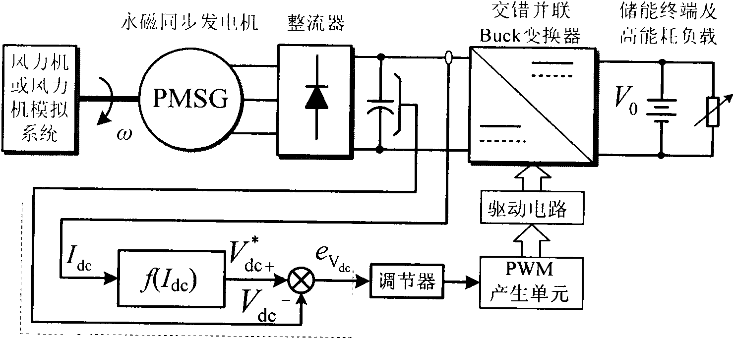
[0047] attached figure 1 The concrete structural block diagram that is realized for the control strategy of the present invention, wherein f(I dc ) The specific implementation of the block diagram is as attached Figure 4 shown in .

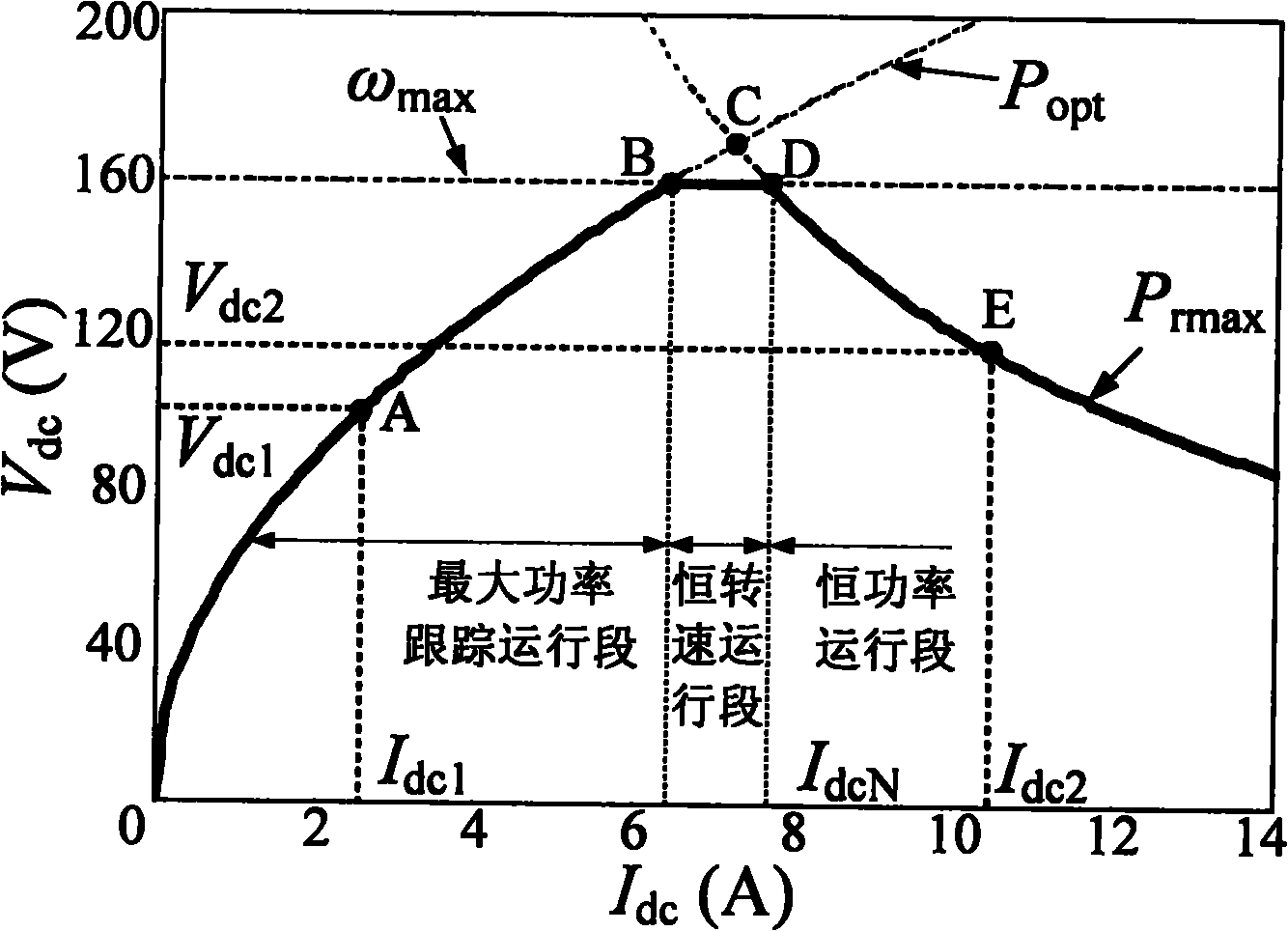
[0048] The maximum power tracking control in the present invention refers to: when the wind power generating set is running in the low wind speed area, as the wind speed changes, the DC bus current changes accordingly, which can be calculated according to formula (9) (attached Figure 4 MPPT block diagram) to calculate the DC bus voltage reference value V required to achieve maximum power tracking dc *, this value is the same as the DC bus voltage feedback value V dc After the difference is adjusted by the regulator, the PWM circuit and the drive circuit generate a duty cycle d to control the DC converter so that the DC bus ...


PUM


Abstract

The invention relates to a wind-speed and rotating-speed sensorless full-wind-speed control strategy suitable for a small and medium sized fixed propeller-pitch variable speed permanent magnet synchronous wind generator set, and belongs to a master control system in the wind power generating control technology. The control strategy provided by the invention mainly comprises firstly, maximum power tracking control in low wind-speed area; secondly, constant power control in high wind-speed area (above rated wind speed); and thirdly, constant rotating-speed soft transition control between the maximum power tracking control and the constant power control. The realization of the control strategy is based on feedback of DC bus-bar voltage signals and DC bus-bar current signals; required DC bus-bar voltage reference value is given according to the change situations of the detected DC bus-bar current, so as to achieve the purpose that output power of the generator set is controlled by controlling the rotating speed of the generator set. Therefore, wind speed and rotational speed signals are not required to be detected in the control strategy, an expensive wind-speed and rotating-speed sensor can be saved, and accordingly, the control cost is greatly reduced, and the strategy has a good application prospect in the small and medium-sized wind generator sets below megawatt class.

Description

technical field [0001] The invention relates to a main control system within the full wind speed range of a fixed-pitch variable-speed wind power generator set using a permanent magnet synchronous generator, which realizes maximum power tracking control and high wind speed control of the unit in a low wind speed area (below the rated wind speed). The constant power control in the zone (above the rated wind speed) and the constant speed soft transition process between the two operating modes. technical background [0002] As the fastest growing renewable energy, wind energy has become an important means to deal with energy crisis and environmental pollution, and it is the focus and hotspot of current research at home and abroad. Although wind turbines (hereinafter referred to as wind turbines) are gradually developing in the direction of high power, variable pitch and variable speed, almost all wind turbines above the megawatt level have adopted this structure. However, due ...

Claims


Application Information

Patent Timeline
Patent Type & Authority Applications(China)
IPC IPC(8): F03D7/00
CPCY02E10/723Y02E10/72
Inventor 陈家伟龚春英陈杰陈冉陈志辉严仰光
Owner NANJING UNIV OF AERONAUTICS & ASTRONAUTICS
Learn More