
'Outside-cylinder series-connection type' non-condensable gas removing device in low-temperature multi-effect distillation seawater desalination system

A technology for removing devices and condensing gas, which is applied in the field of non-condensing gas removing devices, can solve the problems of limiting the improvement of the overall performance of the system and the range of operation adjustment, inconvenient adjustment or replacement, etc., so as to improve the scope of adaptation and facilitate the change of operating conditions , The effect of improving the performance of the device

Active Publication Date: 2011-06-29
CHINA SHENHUA ENERGY CO LTD +3
View PDF5 Cites 3 Cited by
  • Summary
  • Abstract
  • Description
  • Claims
  • Application Information

AI Technical Summary

Problems solved by technology

The above-mentioned non-condensable gas channel orifice plates are installed inside the evaporator, which is not easy to adjust or replace; these orifice plates often require accurate calculations and have fixed dimensions. Once installed, they cannot be adjusted optimally with changes in operating conditions, thus limiting Improved overall system performance and operational adjustment range

Method used


Image

  • 'Outside-cylinder series-connection type' non-condensable gas removing device in low-temperature multi-effect distillation seawater desalination system
  • 'Outside-cylinder series-connection type' non-condensable gas removing device in low-temperature multi-effect distillation seawater desalination system

Examples


Embodiment Construction

[0017] The present invention will now be described in conjunction with the accompanying drawings and specific embodiments, but the present invention is not limited thereto.

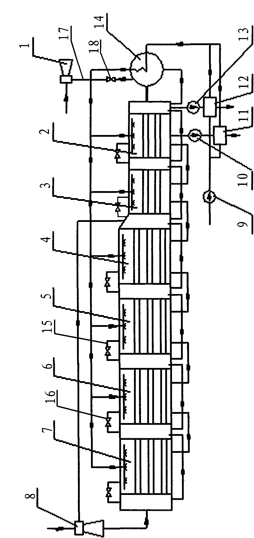
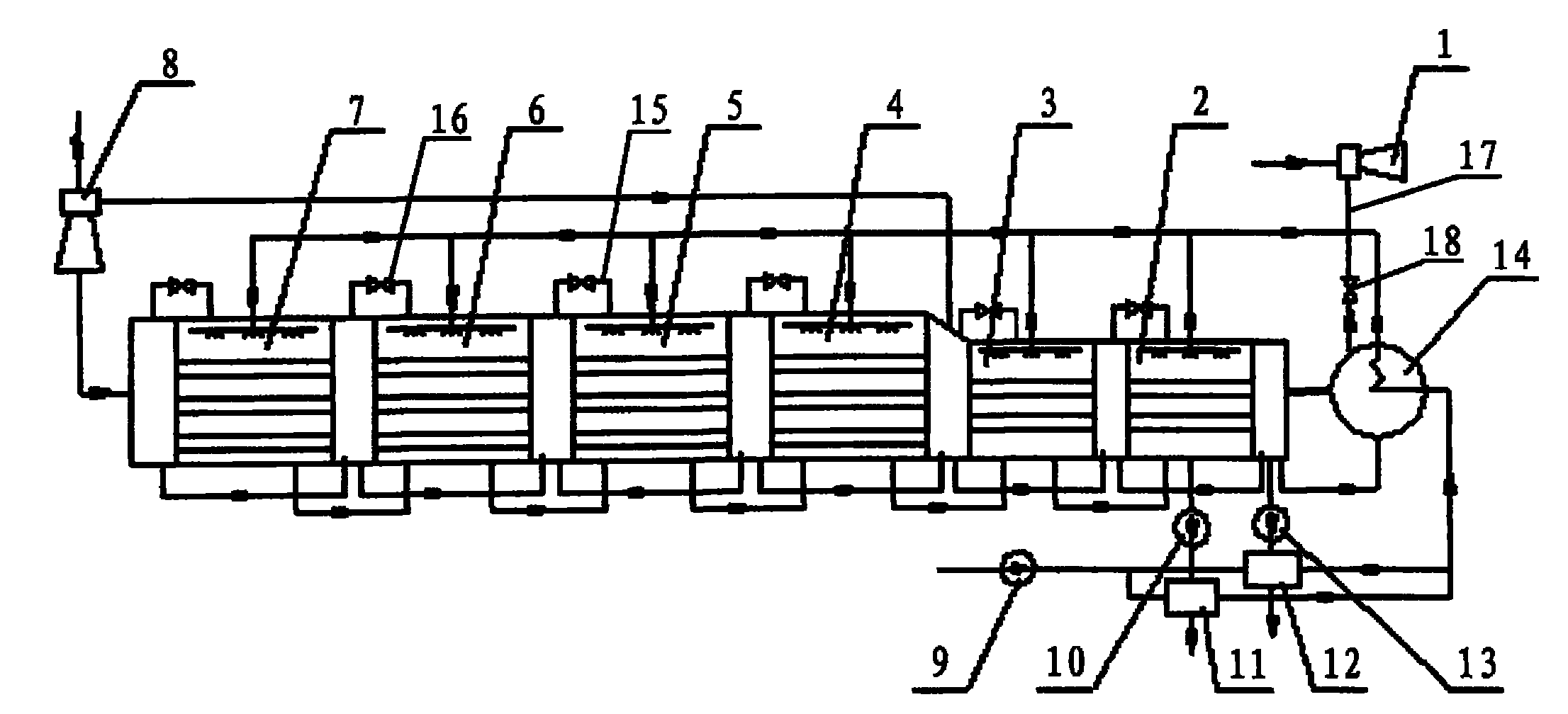
[0018] Low-temperature multi-effect seawater desalination system, including 6-effect evaporator 2-7, steam ejector 8, condenser 14, non-condensable gas removal device, concentrated brine heat exchanger 11, fresh water heat exchanger 12, seawater feed pump 9. Concentrated salt water pump 10, fresh water pump 13. The evaporators of each effect are connected in series end to end in sequence, and the evaporators of each effect are equally divided into a seawater evaporation side and a heating steam side. The heating steam side inlet at the head end of the first effect evaporator 7 is connected to the exhaust port of the steam ejector 8 through a pipeline, and the suction port of the steam ejector 8 is connected to the end of the fourth effect evaporator 4 through a pipeline. The six-effect evaporator 2 is co...


PUM


Abstract

The utility model belongs to the field of seawater desalination, and relates to an 'outside-cylinder series-connection type' non-condensable gas removing device in a low-temperature multi-effect distillation seawater desalination system. The low-temperature multi-effect distillation seawater desalination system comprises evaporators, a steam injector, a steam condenser, the 'outside-cylinder series-connection type' non-condensable gas removing device, a concentrated saltwater heat exchanger, a fresh water heat exchanger, a seawater material feeding pump, a concentrated saltwater pump and a fresh water pump, wherein, the 'outside-cylinder series-connection type' non-condensable gas removing device comprises non-condensable gas communicating pipes, valves arranged on the communicating pipes, a vacuum pumping device, a connecting pipeline for connecting a non-condensable gas extracting opening of the steam condenser and the vacuum pumping device, and a valve arranged on the connecting pipeline; and each non-condensable gas communicating pipe is arranged outside a cylinder body of the corresponding evaporator and respectively connected with a heating steam side and a seawater evaporating side of the corresponding effect evaporator. The low-temperature multi-effect distillation seawater desalination system disclosed by the invention can adjust the non-condensable gas communicating pipes in an on-line manner and control the pressure difference among the effect evaporators, thereby adapting to working condition changes and guaranteeing the matching of the pressure of the effect evaporators.

Description

technical field [0001] The invention belongs to the technical field of seawater desalination, and in particular relates to a device for removing non-condensable gas in a low-temperature multi-effect distillation seawater desalination system. Background technique [0002] When the low-temperature multi-effect seawater desalination system is used for seawater desalination, it is necessary to extract the non-condensable gas (referred to as "non-condensable gas") in the system. There are two main sources of non-condensable gas: one is the release from seawater. There are a certain amount of non-condensable gases dissolved in seawater, including oxygen, nitrogen and carbon dioxide. The low-temperature multi-effect distillation seawater desalination process operates under vacuum conditions. During normal operation, the interior of the entire device is pumped to a vacuum of -70~-90kPa. When the seawater enters the vacuum equipment, part of the gas dissolved in the seawater will b...

Claims


Application Information

Patent Timeline
IPC IPC(8): C02F1/04C02F103/08
CPCY02A20/124
Inventor 周洪光丁涛张忠梅高峰蔡井刚张千牛聚秦张兰芳张鹏
Owner CHINA SHENHUA ENERGY CO LTD
Learn More