Eureka AIR delivers breakthrough ideas for toughest innovation challenges, trusted by R&D personnel around the world.

Sealant coating system adopting two-component distribution system

A two-component, dispensing technology

Active Publication Date: 2011-06-29
SHENZHEN AXXON AUTOMATION
View PDF5 Cites 10 Cited by
  • Summary
  • Abstract
  • Description
  • Claims
  • Application Information

AI Technical Summary

Problems solved by technology

[0005] The object of the present invention is to provide a dispensing system using a two-component dispensing system, which aims to solve the problem of existing switched reluctance

Method used


Image

  • Sealant coating system adopting two-component distribution system
  • Sealant coating system adopting two-component distribution system
  • Sealant coating system adopting two-component distribution system

Examples


Embodiment 1

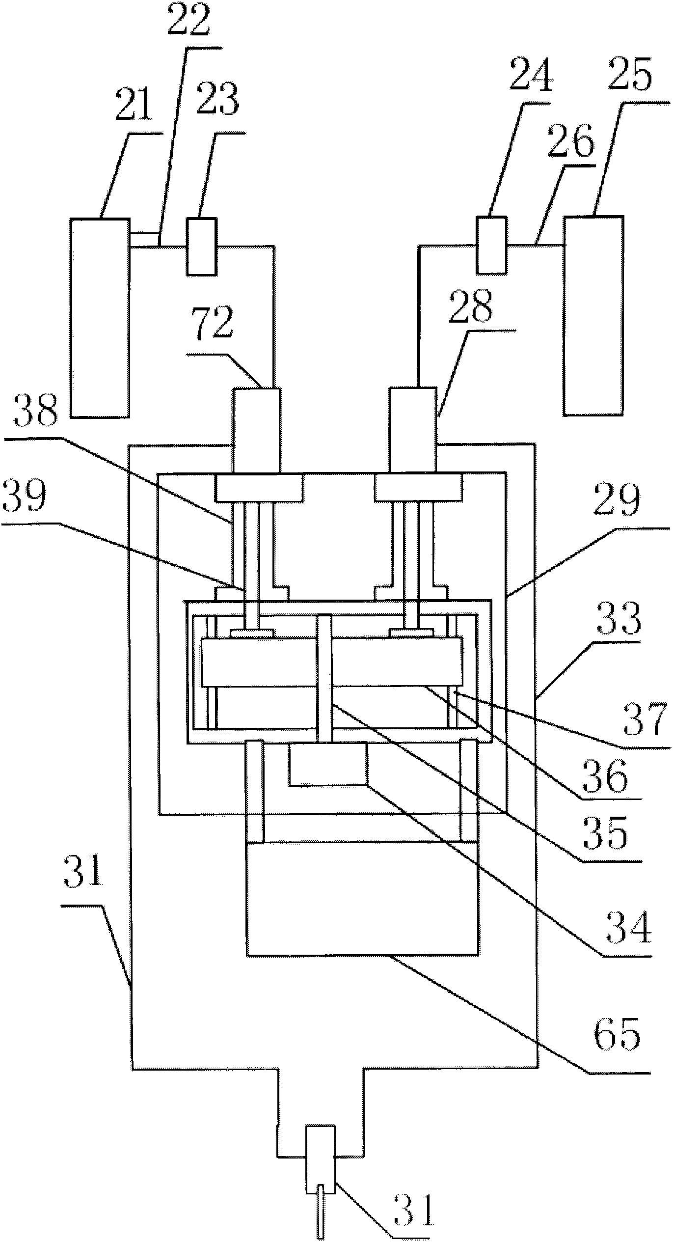
[0039] Such as figure 1 , Figure 4 Figure 5 , Figure 6 As shown, a dispensing system utilizing a two-component dispensing system includes a two-component proportioning system, a first material delivery system 21, a second material delivery system 25, and the first material delivery system 21 through a delivery pipeline 22. The first voltage regulator 23 connected, the second voltage regulator 24 connected to the second material delivery system 25 through the delivery pipeline 26;

[0040] The first voltage stabilizer 23 is connected to the input end of the first reversing device 27 on the two-component proportioning system through the delivery pipeline, and the second voltage stabilizer 24 is connected to the second reversing device 27 on the two-component proportioning system through the delivery pipeline. Connect to the input end of device 72, the output end of the first reversing device 28 is communicated with dispensing device 31 by pipeline, and the second output en...

Embodiment 2

[0062] Such as figure 1 , Figure 4 Figure 5 , Figure 6 As shown, a dispensing system utilizing a two-component dispensing system is characterized in that it includes a two-component proportioning system, a first material delivery system 21, a second material delivery system 25, and a delivery pipeline 22 with the first material The first voltage stabilizer 23 connected to the conveying system 21, the second voltage stabilizer 24 connected to the second material conveying system 25 through the conveying pipeline 26;

[0063] The first voltage stabilizer 23 is connected to the input end of the first reversing device 27 on the two-component proportioning system through the delivery pipeline, and the second voltage stabilizer 24 is connected to the second reversing device 27 on the two-component proportioning system through the delivery pipeline. Connect to the input end of device 72, the output end of the first reversing device communicates with dispensing device through pi...

Embodiment 3

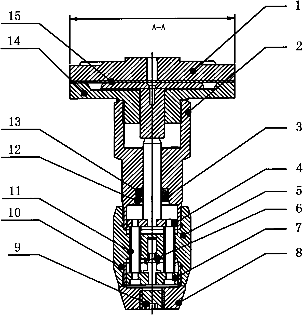
[0068] Such as figure 1 , Figure 4 Figure 5 , Figure 6 As shown, a dispensing system using a two-component dispensing system includes a two-component proportioning system, the first input port of the dispensing valve passes through the delivery pipeline and the input of the first reversing device on the two-component proportioning system The second input port of the dispensing valve is connected to the input end of the second reversing device on the two-component proportioning system through the delivery pipeline.

[0069] The two-component proportioning system includes a base 71, the base 71 is set on at least one frame cylinder 29, two parallel guide posts are the first guide post 37, the second guide post, the first guide post 37, the second guide post The guide pillars are arranged in the frame cylinder body 29, and the two ends of a slide block 36 run through two parallel guide pillars respectively, that is, the first guide pillar 37 and the second guide pillar, whi...


PUM


Abstract

The invention discloses a sealant coating system adopting a two-component distribution system, which comprises a two-component distribution system, a first material delivery system, a second material delivery system, a first voltage stabilizer connected with the first material delivery system through a delivery pipe, and a second voltage stabilizer connected with the second material delivery system through a delivery pipe, wherein the first voltage stabilizer is connected with the input end of a first reversing device on the two-component distribution system through the delivery pipe, the second voltage stabilizer is connected with the input end of a second reversing device on the two-component distribution system through the delivery pipe, the output end of the first reversing device is communicated with a sealant coating device through a pipe, and the output end of the second reversing device is communicated with the sealant coating device through a pipe. When the sealant coating system is used, the sealant coating system can not only fully ensure that the two kinds of sealants are completely blended and completely mixed, but also overcome the problem of poor stability in the prior art by use of the voltage stabilizer systems, and can increase the sealant coating capacity to make the whole sealant coating process more perfect.

Description

technical field [0001] The invention belongs to a dispensing device, in particular to a dispensing system using a two-component distribution system. Background technique [0002] In recent years, in many industrial productions, the commonly used equipment is a two-component gluing machine. This kind of gluing machine has high efficiency, dense glue coating, and consistent vulcanization time on the glass. In order to achieve the above goals, the two-component There are strict requirements on the mixing of two sets of glue in the glue machine. Ordinary two-component glue machines use different pressures on the glue cylinders to control the mixing ratio of the two sets of glue. However, the viscosity of the glue will change with the temperature due to the influence of the ambient temperature during actual use. As the viscosity changes, the flow rate of the glue in the hose will also change. If a fixed pressure is used to control the ratio of the two groups of glue at this time...

Claims


Application Information

Patent Timeline
Patent Type & Authority Applications(China)
IPC IPC(8): B05C5/02B05C11/10
Inventor 杨忠李高勇许洪涛楚善分
Owner SHENZHEN AXXON AUTOMATION
Why Eureka
Eureka Blog
Learn More