Electric power converter
A power conversion device and power supply technology, which is applied to output power conversion devices, electrical components, and AC power input is converted into AC power output, etc., and can solve problems such as low efficiency.
- Summary
- Abstract
- Description
- Claims
- Application Information
AI Technical Summary
Problems solved by technology
Method used
Image

Examples
Embodiment approach 1
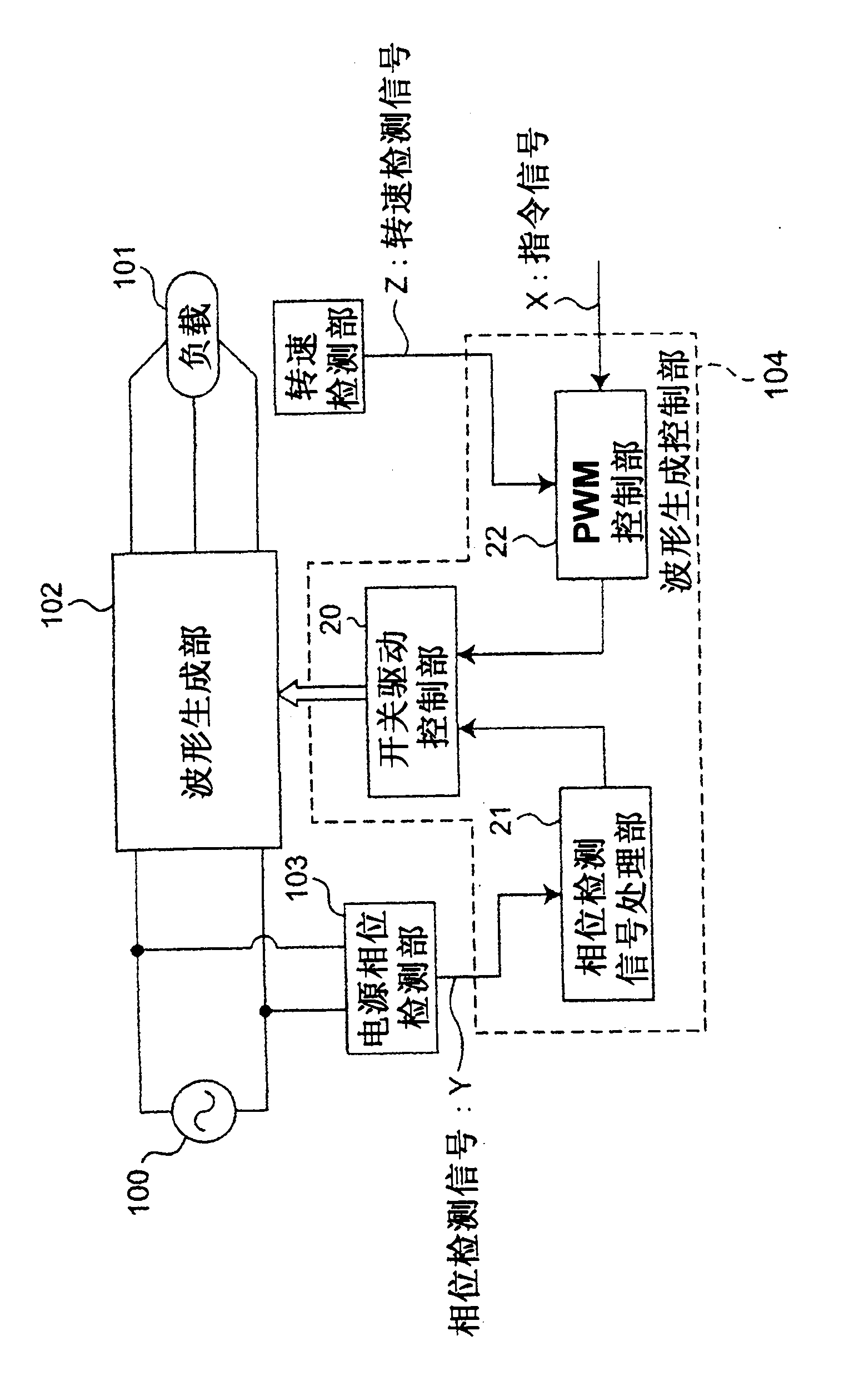
[0070] figure 1 It is a block diagram showing the configuration of the power conversion device according to Embodiment 1 of the present invention. Such as figure 1 As shown, the power conversion device according to Embodiment 1 is a device that directly forms a three-phase AC having a predetermined frequency from a single-phase AC power source 100 to supply three-phase power to a load 101 .
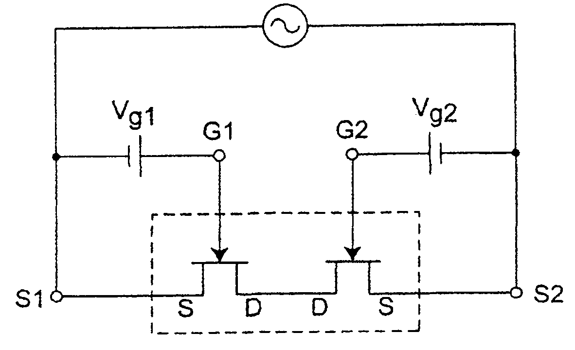
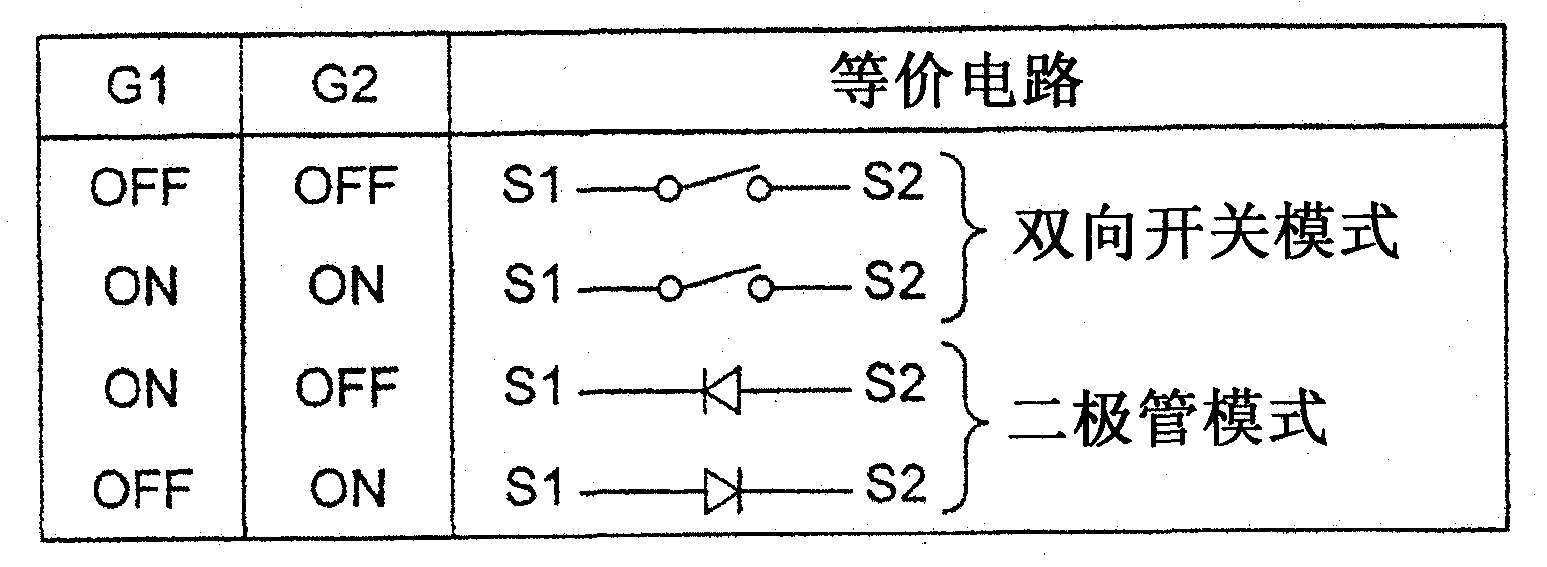
[0071] figure 1 Among them, the single-phase AC input waveform generation unit 102 from the single-phase AC power supply 100 is configured such that the phase of the power supply voltage output from the single-phase AC power supply 100 is detected by the power supply phase detection unit 103 . The predetermined three-phase AC electric power generated by the waveform generation unit 102 is supplied to the load 101 . In Embodiment 1, the load 101 is a motor of an inductive load. As will be described later, the waveform generator 102 is composed of a plurality of bidirectional switchi...
Embodiment approach 2
[0095] Figure 9It is a block diagram showing the configuration of a power conversion device according to Embodiment 2 of the present invention. The power conversion device according to Embodiment 2 is an example of a specific configuration of power supply phase detection unit 103 in the power conversion device according to Embodiment 1 described above. In the power conversion device according to Embodiment 2, the power supply phase detection unit 103 is configured as a voltage phase detection unit 105 that detects the voltage phase of the single-phase AC power supply 100 . In addition, in the power conversion device according to the second embodiment, components having the same functions and structures as those in the power conversion device according to the first embodiment are given the same reference numerals, and the detailed description of the components is applied to the first embodiment. instruction of.
[0096] Such as Figure 9 As shown, bidirectional switching de...
Embodiment approach 3
[0105] Figure 10 It is a block diagram showing the configuration of a power conversion device according to Embodiment 3 of the present invention. In Embodiment 3, components having the same functions and structures as those in Embodiments 1 and 2 are denoted by the same reference numerals, and detailed descriptions of the components apply to those in the respective embodiments.
[0106] The power conversion device according to Embodiment 3 is different from the power conversion device according to Embodiment 2 in that the voltage phase detection unit 105 that detects the voltage phase of the single-phase AC power supply 100 is replaced by a current phase detection unit 105 that detects the single-phase AC power supply 100 . The current phase detection part 107.
[0107] Such as Figure 10 As described above, in the power conversion device according to Embodiment 3, the single-phase AC power supply 100 , the three-phase load 101 , and the waveform generator 102 constitute a ...
PUM
 Abstract
Description
Claims
Application Information
 - R&D
- Intellectual Property
- Life Sciences
- Materials
- Tech Scout
- Unparalleled Data Quality
- Higher Quality Content
- 60% Fewer Hallucinations
Browse by: Latest US Patents, China's latest patents, Technical Efficacy Thesaurus, Application Domain, Technology Topic, Popular Technical Reports.
© 2025 PatSnap. All rights reserved.Legal|Privacy policy|Modern Slavery Act Transparency Statement|Sitemap|About US| Contact US: help@patsnap.com