Utilization method of fluid energy in water supply pipe network and power generation system of water supply pipe network

A water supply network and fluid technology, applied in water supply pipeline systems, hydropower, hydropower stations, etc., can solve the problem of inestimable accumulative available energy and achieve significant economic benefits

Inactive Publication Date: 2011-06-22
孙盛荣
View PDF3 Cites 3 Cited by
  • Summary
  • Abstract
  • Description
  • Claims
  • Application Information

AI Technical Summary

Problems solved by technology

It can be seen that the water energy that can be reused by only one water plant in Dalian is quite considerable, and the cumulative energy that can be used in the whole country is immeasurable.

Method used


Image

  • Utilization method of fluid energy in water supply pipe network and power generation system of water supply pipe network
  • Utilization method of fluid energy in water supply pipe network and power generation system of water supply pipe network
  • Utilization method of fluid energy in water supply pipe network and power generation system of water supply pipe network

Examples


Embodiment Construction

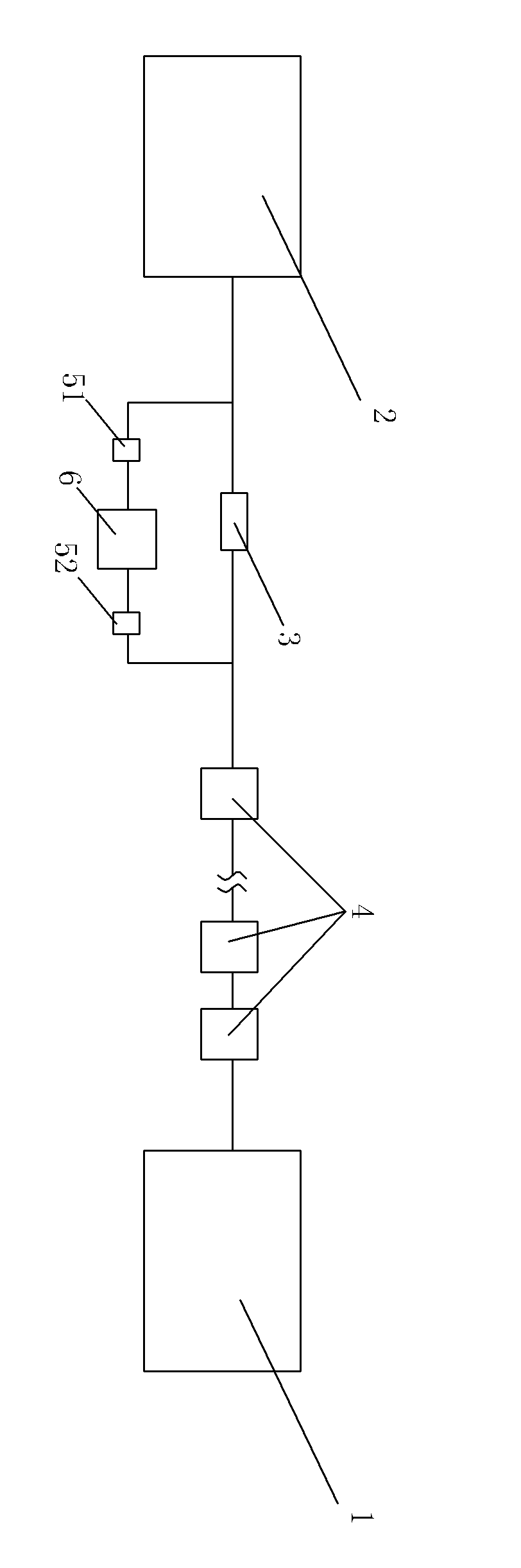
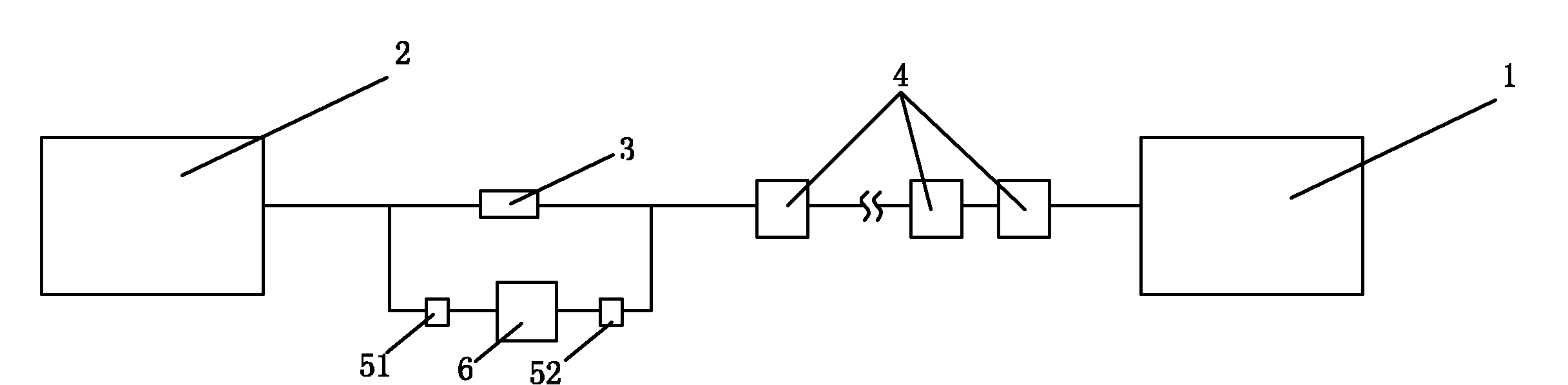
[0016] Such as figure 1 A pipeline fluid energy power generation system is shown, in which multiple pressurization stations 4 are installed between the water source 1 and the water intake 2 of the water plant. The water source 1, the pressurization station 4 and the water intake 2 of the water plant are all connected by a pipe network or a ditch. A two-way valve 3 is installed on the pipeline at the 2 water intake of the water plant, and a pipe is connected in parallel at both ends of the valve 3. network branch; a power generation system is installed on the branch; the power generation system includes a generator 6, and the two ends of the generator 6 are respectively equipped with a first valve 51 and a second valve 52; wherein, the generator 6 is connected in series with the first valve 51 and the second valve 52 in the pipe network branch. In a preferred manner, the generator 6 is a hydroelectric generator.

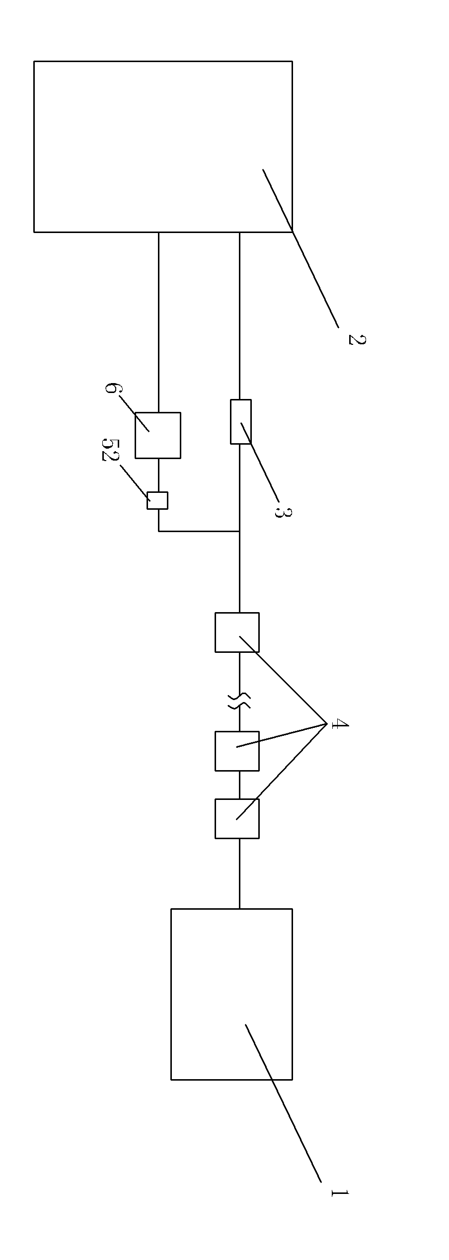
[0017] Such as figure 2 As shown, the second water supply pi...


PUM


Abstract

The invention relates to a utilization method of the fluid energy in a water supply pipe network. A power generator is additionally arranged at a water intake of a water plant, particularly, the water intake of the water plant comprises a first branch provided with a first valve/sluice 3 and a second branch which is connected in parallel with the first branch and is sequentially provided with a second valve/sluice 52 and the power generator 6 along the flow direction, wherein the first branch is directly led to a pool of the water plant, and the second branch is also directly led to a pool or is connected to a water outlet pipeline of the first branch after passing through the second valve/sluice 52. The invention has the advantages that a power generation system is suitable for a transmission pipe network of water, gas and oil, a power generator can utilize the fluid energy to generate the power by connecting the power generation system with a pipe network mainstream pipeline in parallel, and the normal production and the use of a fluid can not be influenced although the power generator has a fault, therefore, the invention truly realizes zero discharge and zero pollution.

Description

technical field [0001] The invention relates to the transformation of the water pipe network, more specifically, to the transformation of the source water pipe network of the water plant. Background technique [0002] Under the existing technology, people use the pipe network to transport water over long distances to the water intake of the water plant. The water that reaches the water intake of the water plant carries energy, and the energy is not used and wasted directly. Take the waterworks in Shahekou District, Dalian as an example. In order to solve the problem of urban water sources, waterworks generally need to draw water from rivers or reservoirs at least 100 kilometers away. There is a drop between the highest point of the water plant and the water intake of the water plant. We know that water with a drop has energy. Taking Dalian Shahekou Water Plant as an example, it needs 400,000 tons of water per day, so the flow rate per second is 4.6 cubic meters. If the net ...

Claims


Application Information

Patent Timeline
Patent Type & Authority Applications(China)
IPC IPC(8): F03B13/00E02B9/02E03B7/02E03B7/07
CPCY02E10/22Y02E10/20Y02P70/50
Inventor 孙盛荣
Owner 孙盛荣
Why Eureka
Try Eureka