
Device and method for processing valve core

A processing device and processing method technology, applied in metal processing, metal processing equipment, manufacturing tools, etc., can solve the problems of reducing the strength of the valve core, difficult to control product quality, and air leakage of the valve core, so as to improve the service life and save labor costs. , the effect of improving dimensional accuracy

Inactive Publication Date: 2011-06-22
张良羽
View PDF7 Cites 1 Cited by
  • Summary
  • Abstract
  • Description
  • Claims
  • Application Information

AI Technical Summary

Problems solved by technology

[0003] The purpose of the present invention is to provide a valve core processing device and method, which can effectively solve the problems that the existing process holes on the valve core will reduce the strength of the valve core, cause air leakage of the valve core, large workpiece size error, and difficult to control product quality. question

Method used


Image

  • Device and method for processing valve core
  • Device and method for processing valve core
  • Device and method for processing valve core

Examples


Embodiment Construction

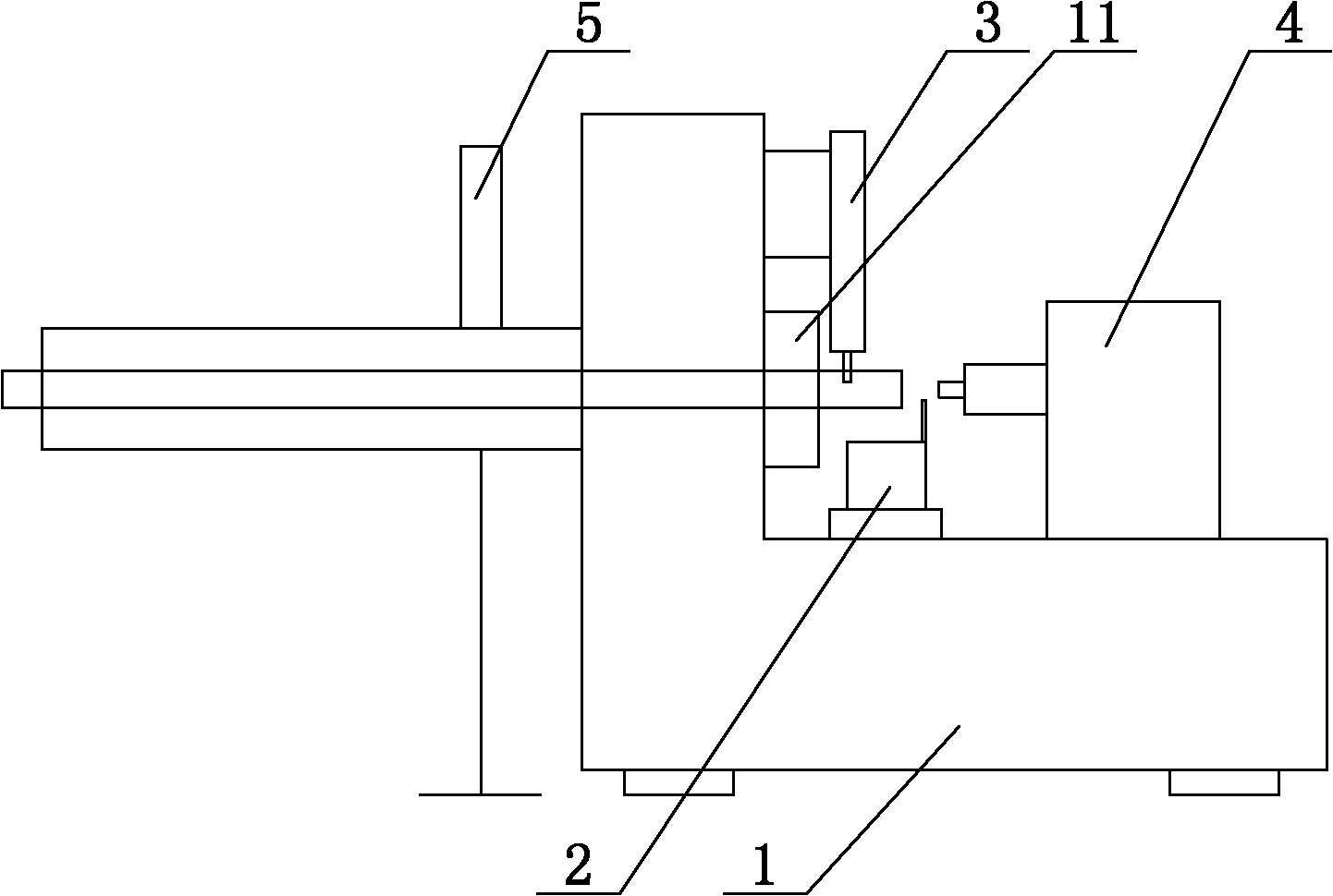
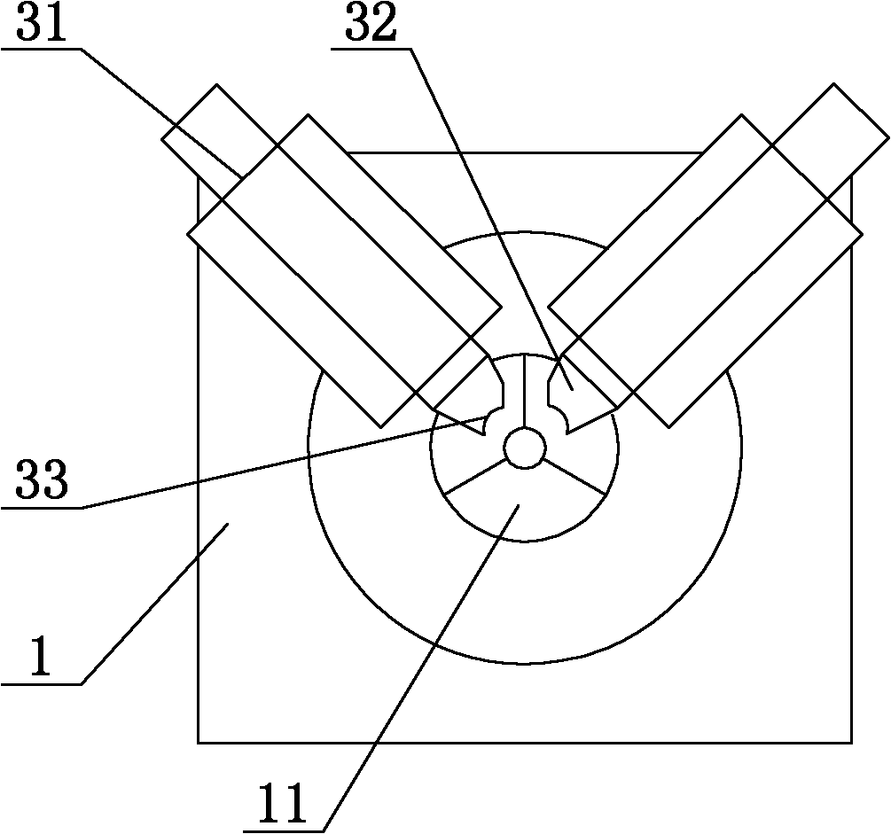
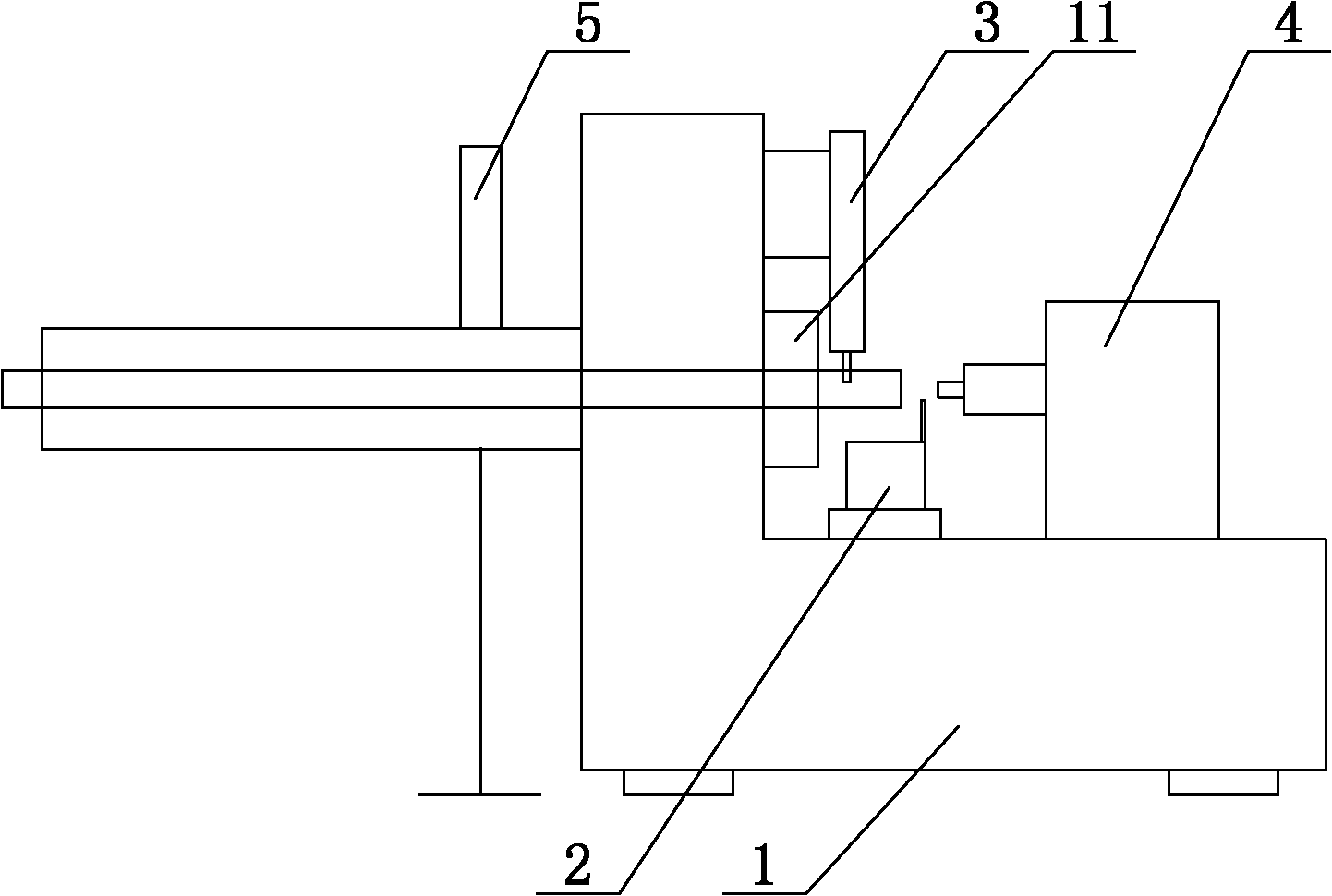
[0020] refer to figure 1 , figure 2 It is an embodiment of a valve core processing device of the present invention. A valve core processing device includes a lathe 1, and the lathe 1 is provided with a bar clamping device 11, and also includes a knife seat 2, a stamping locking device 3, The hydraulic tailstock 4, the tool holder 2 and the hydraulic tailstock 4 are all slidably arranged on the guide rail at the right part of the lathe 1, and the stamping locking device 3 is arranged at the right end of the bar material clamping device 11 on the lathe 1. The stamping locking device 3 includes two hydraulic cylinders 31, the front section of the hydraulic cylinder 31 is provided with a locking head 32 for locking the bar, and the front end of the locking head 32 is provided with an arc-shaped Groove 33, the included angles between the two hydraulic cylinders 31 and the horizontal plane are respectively 45 degrees and 135 degrees, and the tool holder 2 is provided with at least...


PUM


Abstract

The invention discloses a device for processing a valve core, which comprises a lathe, wherein a rod clamping device is arranged on the lathe, and the device further comprises a tool apron, a stamping and locking device and a hydraulic tailstock, wherein the tool apron and the hydraulic tailstock are arranged on a guide rail at the right part of the lathe in a sliding manner, and the stamping and locking device is arranged at the right end of the rod clamping device on the lathe. The method for processing the valve core comprises the following steps: firstly clamping a rod, drilling a circular blank hole at the end part of the rod, well cutting an annular groove at the front end, cutting a fixed groove at the tail end, clamping the stamping and locking device in the fixed groove, using the hydraulic tailstock to punch the circular blank hole into a hexagonal inner hole, further processing a thread, and finally cutting off the well processed valve core. The method has the advantages that the positioning is performed only once, the size precision of the valve core is improved, the valve core after processing simultaneously has no process holes, the service life of the valve core is prolonged, the air leakage problem is difficult to occur, a worker can simultaneously operate multiple machines, and the labor cost is also saved.

Description

technical field [0001] The invention relates to a valve core processing device and method. Background technique [0002] The spool used in the thermal expansion valve in the air conditioner is generally cylindrical, with a hole with a regular hexagonal longitudinal section on one end, and threads and at least one circular groove on the outer cylindrical surface of the spool. The existing processing method is to first cut the bar stock into sections of blanks, drill holes on the end face, then put them into a punching machine to punch the holes into hexagonal holes, and then process grooves and threads on a lathe. The top is positioned on the other end surface, but a process hole will be left on the end surface after the car is finished. This process hole will reduce the strength of the valve core and easily cause the valve core to leak. Moreover, such processing needs to be performed on the valve core many times. Positioning, resulting in a large dimensional error of the sp...

Claims


Application Information

Patent Timeline
Patent Type & Authority Applications(China)
IPC IPC(8): B23Q37/00B23P15/00
Inventor 张良羽郑建龙孙敬成
Owner 张良羽
Learn More