Optical line terminal for wavelength division multiplexing-time division multiplexing passive optical network
A passive optical fiber network, optical line terminal technology, applied in the selection device of multiplexing system, electromagnetic wave transmission system, electromagnetic transceiver and other directions, can solve problems such as cost pressure, and achieve the effect of improving bandwidth bottleneck and low cost
Inactive Publication Date: 2011-06-15
SHENZHEN GIGALIGHT TECH
View PDF2 Cites 7 Cited by
- Summary
- Abstract
- Description
- Claims
- Application Information
AI Technical Summary
Problems solved by technology
However, WDMPON technology has certain cost pressures, mainly from optical components
Method used
View moreImage
Smart ImageViewing Examples
Examples
Embodiment Construction
Login to View More PUM
 Abstract
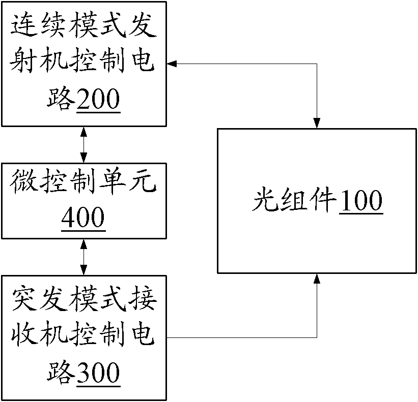
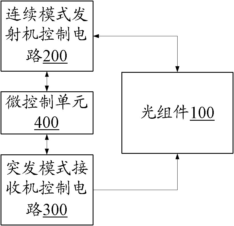
The invention relates to an optical line terminal for a wavelength division multiplexing-time division multiplexing passive optical network. The optical line terminal comprises an optical sub-assembly, a continuous mode transmitter control circuit, a burst mode receiver control circuit, and a micro control unit, wherein the continuous mode transmitter control circuit is connected with the optical sub-assembly, and controls the light-emitting state of the optical sub-assembly; the burst mode receiver control circuit is connected with the optical sub-assembly to provide a working voltage for the optical sub-assembly, and receives an electrical signal of the optical sub-assembly; and both the continuous mode transmitter control circuit and the burst mode receiver control circuit are connected with the micro control unit, and are controlled and monitored by the micro control unit. The optical line terminal has the continuous mode transmitter control circuit for transmitting the optical signal and the burst mode receiver control circuit for processing the burst uplink optical signal, and is applied to a wavelength division multiplexing-time division multiplexing (WDM-TDM) passive optical network. Compared with the method for improving the bandwidth bottleneck by adopting the WDM simply, the optical line terminal for the wavelength division multiplexing-time division multiplexing passive optical network has lower cost.
Description
Optical Line Termination for WDM-TDM Passive Optical Networks 【Technical field】 The invention relates to a passive optical fiber network, in particular to an optical line terminal of a wavelength division multiplexing-time division multiplexing passive optical fiber network. 【Background technique】 The fact that passive optical network technology is the technology of choice for fiber access networks is widely accepted. At present, the main implementation form of passive optical network technology is time division multiplexing mode, namely time division multiplexing passive optical network (TDMPON). TDMPON uplink adopts time-division multiplexing, and each optical network unit (ONU) at the user end uploads optical signals in a designated time slot without interfering with each other. The downlink of TDM-PON adopts the broadcast mode, and each ONU can only recognize the information segment of the corresponding identifier in the continuous optical signal downlinked by the op...
Claims
Login to View More Application Information
Patent Timeline
 Patent Type & Authority Applications(China)
IPC IPC(8): H04B10/14H04Q11/00H04B10/40
Inventor 王侃陈涛
Owner SHENZHEN GIGALIGHT TECH
Features
- R&D
- Intellectual Property
- Life Sciences
- Materials
- Tech Scout
- Unparalleled Data Quality
- Higher Quality Content
- 60% Fewer Hallucinations
Learn More Browse by: Latest US Patents, China's latest patents, Technical Efficacy Thesaurus, Application Domain, Technology Topic, Popular Technical Reports.
© 2025 PatSnap. All rights reserved.Legal|Privacy policy|Modern Slavery Act Transparency Statement|Sitemap|About US| Contact US: help@patsnap.com


