
Method and system for rapidly optimizing drawing technology of photonic crystal fiber

A photonic crystal fiber, rapid technology, applied in manufacturing tools, glass manufacturing equipment, etc., can solve the problems of inability to optimize the drawing process parameters, insufficient analysis of the slight deformation of the photonic crystal fiber, etc., to shorten the development cycle, shorten the development time, fast effect

Inactive Publication Date: 2011-06-15
BEIJING JIAOTONG UNIV
View PDF2 Cites 7 Cited by
  • Summary
  • Abstract
  • Description
  • Claims
  • Application Information

AI Technical Summary

Problems solved by technology

Because the physical field model is difficult to completely simulate the actual fiber drawing environment, and the equation is simplified a lot in order to solve the complex N-S equation during the analysis of the model, so this analysis method is only a theoretical method, not enough Analysis of slight deformations often seen in photonic crystal fibers in complex drawing environments
This theoretical analysis method cannot guide the optimization of actual drawing process parameters.

Method used


Image

  • Method and system for rapidly optimizing drawing technology of photonic crystal fiber
  • Method and system for rapidly optimizing drawing technology of photonic crystal fiber
  • Method and system for rapidly optimizing drawing technology of photonic crystal fiber

Examples


Embodiment 1

[0058] image 3 A schematic cross-sectional view of the design structure of the photonic crystal fiber according to Embodiment 1 of the present invention is shown. The photonic crystal fiber in Example 1 is a five-circle air hole fiber with a diameter of 125 mm made of pure silica as the background material, and its design characteristic is that only the fundamental mode can be effectively transmitted during transmission.

[0059] For example, the preform rod of the photonic crystal fiber is fabricated by the tube rod stacking method, and the diameter of the preform rod is 18 mm. One end of the preform is fixed on the feeding device of the optical fiber drawing device 1001, and the other end of the preform is heated in the heating device. The molten part of the preform in the heating device is pulled by the pulling device to form a bare optical fiber. First, process parameters are selected based on experience, for example: furnace temperature 1950°C, feeding speed 0.3mm / min,...

Embodiment 2

[0082] Figure 12 It shows a cross-sectional schematic diagram of a design structure of a dispersion-compensated photonic crystal fiber with a negative dispersion central wavelength of 1550 nm according to Embodiment 2 of the present invention, and the design requirement of the fiber is to have a large negative dispersion performance around 1550 nm. The background material of the photonic crystal fiber is, for example, pure silica, and the central region is, for example, germanium-doped silica as a high-refractive-index core. The prefabricated rod is produced by the tube rod stacking method, and the diameter of the preset rod is 18mm. During the drawing process, air is drawn from the gap between the thin tube and the thin rod, and the air is inflated into the thin tube at the same time. One end of the preform is fixed on the feeding device of the optical fiber drawing equipment, and the other end enters the heating device for heating, and the molten part of the preform is pull...


PUM

PropertyMeasurementUnit
refractive indexaaaaaaaaaa

Abstract

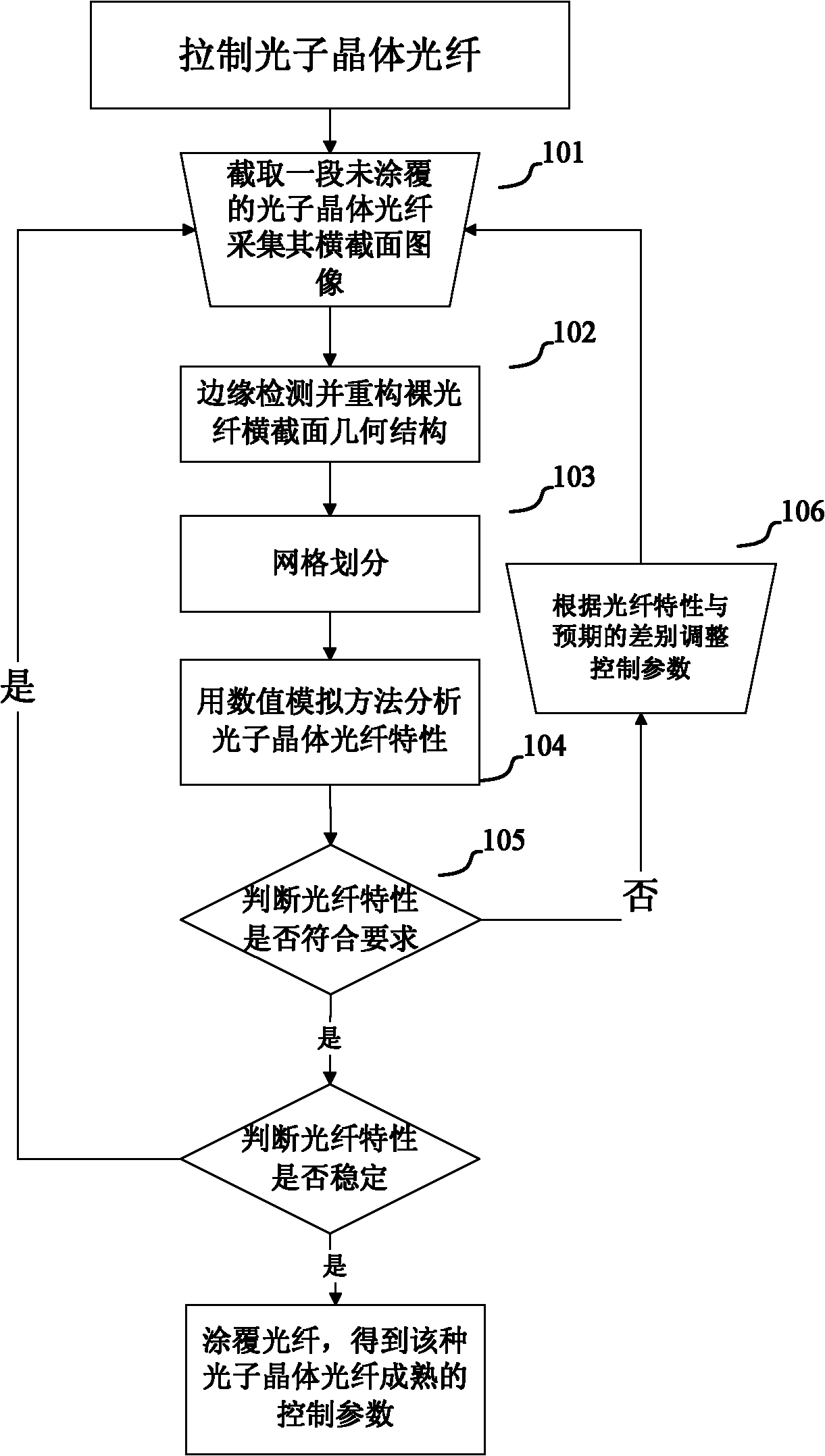
The invention relates to a method for rapidly optimizing the drawing technology of the photonic crystal fiber. The method comprises the following steps in the drawing process of the photonic crystal fiber: cutting off a drawn and uncoated bare fibre, collecting the cross-sectional image of the drawn bare fibre; performing edge detection to the cross-sectional image of the bare fibre, reconstructing the geometrical structure of the cross section of the bare fibre; meshing the inside area of the cross section according to the reconstructed geometrical structure; adopting the numerical simulation method to analyze the photonic crystal fiber characteristics of the bare fibre; and comparing the analytical characteristics of the bare fibre with the design characteristics of the photonic crystal fiber to obtain a comparison result; adjusting the drawing technological parameters of the photonic crystal fiber according to the comparison result; and repeating the steps to ensure that the differences between the analytical characteristics of the drawn bare fibre and the design characteristics can be ignored and obtain a group of the optimized technological parameters for drawing the photonic crystal fiber.

Description

technical field [0001] The invention relates to an optical fiber manufacturing method and system, in particular to an optimized photonic crystal optical fiber drawing process method and system. Background technique [0002] Since the successful development of photonic crystal fiber was reported in 1996, it has attracted much attention because of its flexible structure design and novel characteristics. By designing different air hole structures, photonic crystal fibers can obtain many unmatched characteristics of ordinary single-mode fibers, such as endless single-mode, high birefringence, high nonlinearity, super-large mode field area, and super-flat dispersion, making them widely used in optical fiber communication, Fiber optic gyroscopes, fiber optic sensors, fiber lasers and other fields have great application potential. [0003] The flexible and complex structure of photonic crystal fiber brings various novel properties, but also increases the difficulty of the drawing ...

Claims


Application Information

Patent Timeline
Patent Type & Authority Applications(China)
IPC IPC(8): C03B37/02C03B37/03
Inventor 王立文娄淑琴陈卫国李宏雷苏伟
Owner BEIJING JIAOTONG UNIV
Learn More