


Quick Research
Generate reliable direction feasibility study reports for your R&D in just a few steps.

Technical Q&A
Discover and master advanced knowledge NOW. Basics, ideas, possibilities, all at once.

Find Solutions
As an expert in R&D theories, this can generate solutions to your technical problems instantly.

Evaluate Feasibility
Analyze your overall solution with one click, know your potential R&D risks in advance.

Monitor Landscape
Get weekly tech updates, stay abreast of the latest tech innovations and key insights.
Capacitor charge pump
A charge pump, capacitive technology, used in electrical components, conversion equipment without intermediate conversion to AC, and output power conversion devices, etc. The effect of simple voltage circuit, small number of capacitors and high efficiency
- Summary
- Abstract
- Description
- Claims
- Application Information
AI Technical Summary
Problems solved by technology
Method used
Image


Examples
Embodiment 1
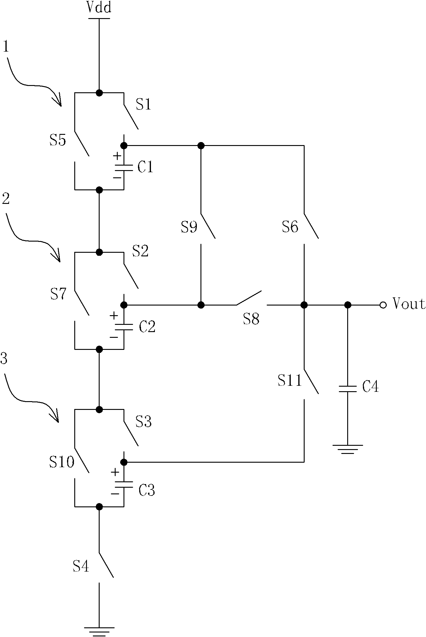
[0046] figure 1 It is a schematic diagram of the first embodiment of the present invention. There are three pumping circuits 1 to 3 in the figure, each pumping circuit includes a flying capacitor and two switches; pumping circuit 1 has capacitor C1 and switches S1, S5; pumping circuit 2 has capacitor C2 and switches S2, S7 , the pump stage circuit 3 has a capacitor C3 and switches S3 and S10. There is another switch network, which is composed of S9, S6, S8 and S11, and these three pump stage circuits in series together form a boost circuit. Another C4 is connected in parallel to filter between the output terminal Vout and the ground. For the convenience of description, the positive and negative terminals of the capacitors C1 to C3 are marked according to their initial charging and discharging polarities.
[0047] The realization of the flying capacitor is to rely on the opening and closing of each switch to make the capacitor form different charging and discharging networks...
Embodiment 2
[0061] In practical applications, the switch works at a higher frequency, usually using a control device with a switching function. Now, in a system on chip, a switching MOS tube can perform such a switching function. Such as Figure 6 In the circuit diagram of the second embodiment shown, this embodiment is integrated on the chip to achieve a small volume, and all MOS transistors are enhanced.
[0062] Basically, the source and drain of all MOS tubes directly replace the original figure 1 The position of the middle switch is different from the MOS transistor M6, which is realized by parallel connection of the sources and drains of four MOS transistors M61, 62, 63, and 64 with the same parameters.
[0063] Of course, to achieve Figure 6 For the functionality of the on-chip circuitry shown, there must also be a range of peripherals. Such as Figure 7 As shown, the boost circuit box in the figure is Figure 6 The content in the other is the external facilities commonly use...
PUM
 Abstract
Description
Claims
Application Information
 - R&D Engineer
- R&D Manager
- IP Professional
- Industry Leading Data Capabilities
- Powerful AI technology
- Patent DNA Extraction
Browse by: Latest US Patents, China's latest patents, Technical Efficacy Thesaurus, Application Domain, Technology Topic, Popular Technical Reports.
© 2024 PatSnap. All rights reserved.Legal|Privacy policy|Modern Slavery Act Transparency Statement|Sitemap|About US| Contact US: help@patsnap.com