


Quick Research
Generate reliable direction feasibility study reports for your R&D in just a few steps.

Technical Q&A
Discover and master advanced knowledge NOW. Basics, ideas, possibilities, all at once.

Find Solutions
As an expert in R&D theories, this can generate solutions to your technical problems instantly.

Evaluate Feasibility
Analyze your overall solution with one click, know your potential R&D risks in advance.

Monitor Landscape
Get weekly tech updates, stay abreast of the latest tech innovations and key insights.
Fuel supply system having pressure control valve
A fuel supply system and high-pressure fuel technology, applied in the field of pressure control valves, can solve the problems of fuel consumption, deterioration of starting performance, and insufficient completion of fuel pressurization.
- Summary
- Abstract
- Description
- Claims
- Application Information
AI Technical Summary
Problems solved by technology
Method used
Image

Examples
no. 1 approach
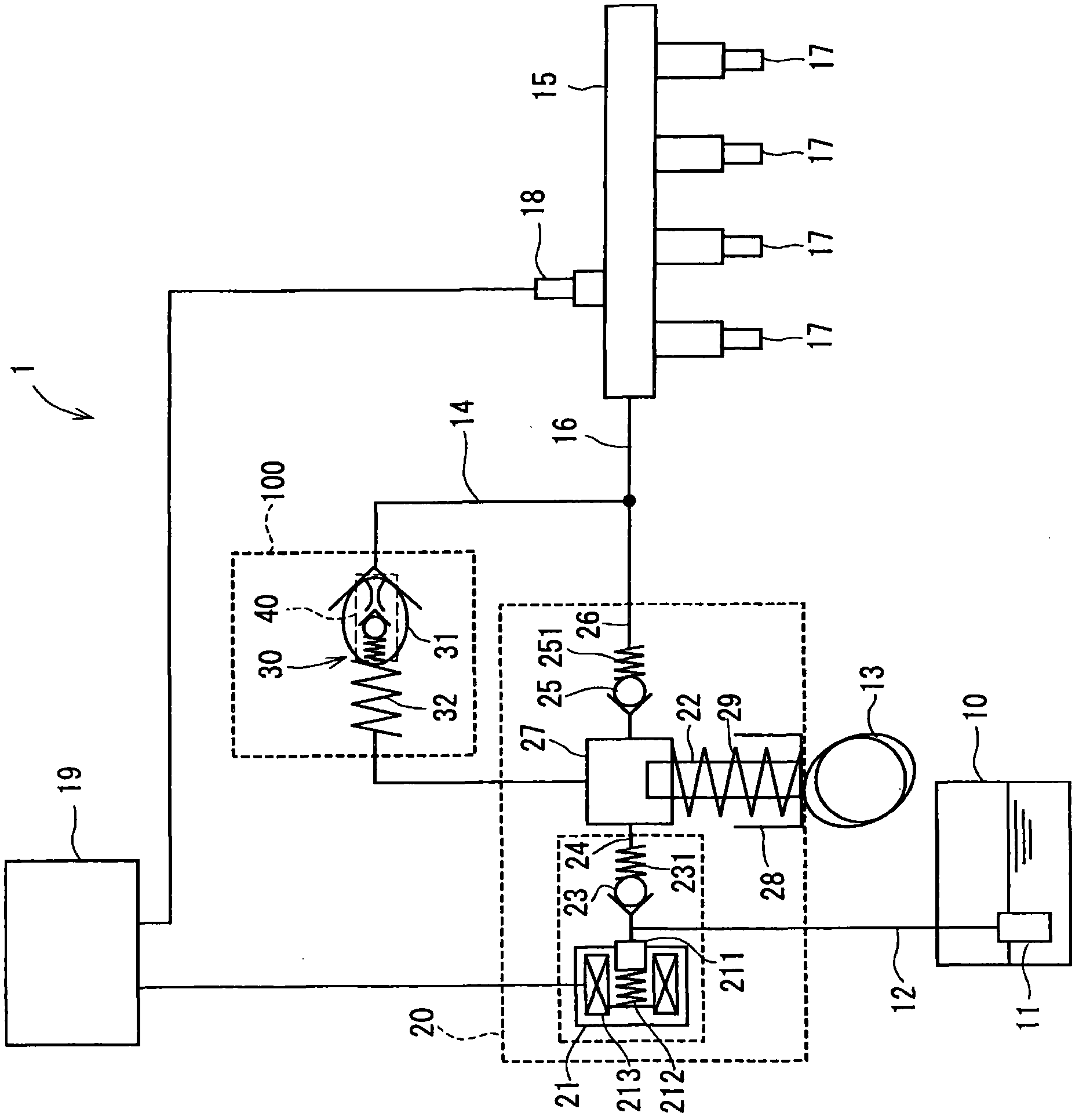
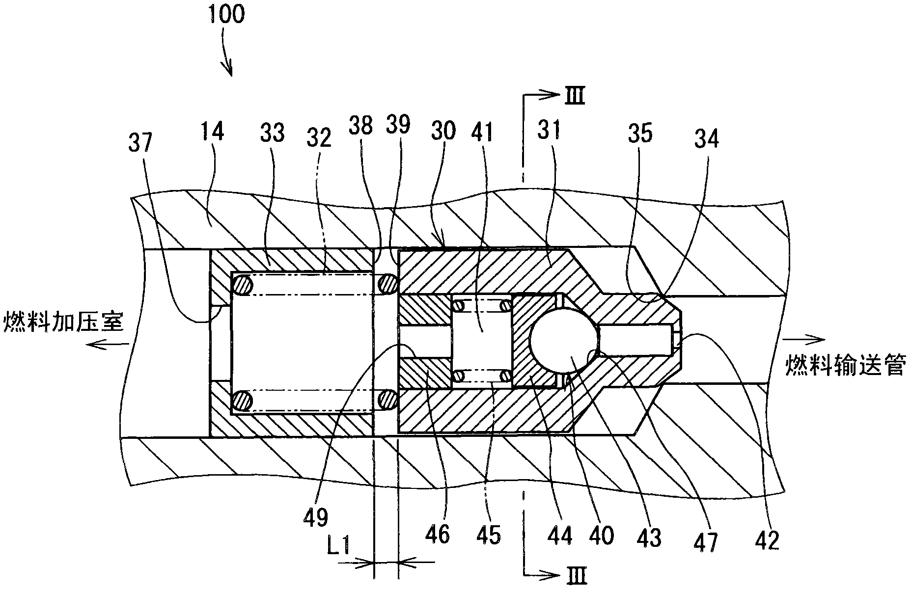
[0071] The fuel supply system to which the pressure control valve according to the first embodiment of the present invention is applied is a fuel supply system 1 for a direct injection type internal combustion engine in which fuel is directly injected to the in the cylinder (combustion chamber). Such as figure 1 As shown, the fuel supply system 1 includes a fuel tank 10, a high-pressure pump 20, a fuel delivery pipe 15, a fuel injection device (injector) 17, a pressure relief valve 30, a pressure maintaining valve 40 (also called a constant residual pressure valve), A fuel pressure sensor 18, a controller (electronic control unit) 19, and the like. The pressure control valve 100 includes a pressure relief valve 30, a pressure maintaining valve 40, and the like.
[0072] Fuel is drawn from a fuel tank 10 by a low-pressure fuel pump 11 and supplied to a high-pressure fuel pump 20 via a low-pressure fuel pipe 12 . Fuel is pressurized by a high-pressure fuel pump 20 and supplie...
no. 2 approach
[0146] will refer to Figure 10A and 10B A fuel supply system to which the pressure control valve according to the second embodiment of the present invention is applied is explained.
[0147] According to the second embodiment, when the controller 19 determines at step S4 that the flag for the abnormal situation stored in the memory is "1", that is, "Yes" at step S4, until the fuel in the fuel delivery pipe 15 The process continues until the pressure becomes higher than a predetermined value ( Figure 10B , "No" at step S6), then the fuel pressure in the fuel delivery pipe 15 becomes higher than a predetermined value ( Figure 10B , YES at step S6), the process shifts to cleaning mode operation.
[0148] The predetermined value here refers to a pressure close to but lower than the first pressure. Furthermore, the predetermined value refers to a pressure in the fuel delivery pipe 15 close to the maximum fuel injection pressure for the injection 17 during acceleration of the...
no. 3 approach
[0151] will refer to Figure 11 A pressure control valve according to a third embodiment of the present invention is explained. The shapes of the stopper 50 and the first spring 55 of the relief valve 30 according to the third embodiment are different from those in the first embodiment.
[0152] The stopper 50 is formed in a cylindrical shape having a large diameter portion 51 and a small diameter portion 52 . The outer peripheral wall of the large-diameter portion 51 is fixed to the inner peripheral wall of the fuel return pipe 14 . The small-diameter portion 52 extends from one end of the large-diameter portion 51 in the direction toward the fuel delivery pipe 15 .
[0153] A first through hole 53 is formed in the stopper 50 , the first through hole 53 extending in the axial direction thereof so that both axial end spaces thereof communicate with each other. A second through hole 54 is formed in the small diameter portion 52 , wherein the second through hole 54 extends in...
PUM
 Abstract
Description
Claims
Application Information
 - R&D Engineer
- R&D Manager
- IP Professional
- Industry Leading Data Capabilities
- Powerful AI technology
- Patent DNA Extraction
Browse by: Latest US Patents, China's latest patents, Technical Efficacy Thesaurus, Application Domain, Technology Topic, Popular Technical Reports.
© 2024 PatSnap. All rights reserved.Legal|Privacy policy|Modern Slavery Act Transparency Statement|Sitemap|About US| Contact US: help@patsnap.com