
Worm-gear speed-reducing wire-feeding motor equipment as well as wire feeding device provided with same and welding system provided with same

A technology of worm gear and motor equipment, which is applied in the direction of electromechanical devices, arc welding equipment, welding equipment, etc., can solve the problems that affect the working accuracy and product life, the motor cannot work normally, and the dynamic response speed is slow, so as to ensure stable and high precision Normal operation, prevent the motor from malfunctioning, and improve welding quality and efficiency

Active Publication Date: 2011-05-25
贝姆勒精密机电(厦门)有限公司
View PDF4 Cites 4 Cited by
  • Summary
  • Abstract
  • Description
  • Claims
  • Application Information

AI Technical Summary

Problems solved by technology

[0002] The existing wire feeding motors and wire feeding devices for welding wire feeding mainly have the following disadvantages: (1) The motor adopts a long cylindrical brushed permanent magnet DC motor, which not only slows the dynamic response speed, but also shortens the life of the wire feeding motor products. Seriously affected by the short life of the long cylindrical brushed permanent magnet DC motor; (2) The output end bearing structure of the deceleration transmission device is unreasonable, and it is very easy to cause the inner ring or outer ring of the output end bearing to match the matching parts in practical applications. Relative sliding occurs on the surface of the bearing, which leads to the premature failure of the rolling bearing function of the output bearing and affects the working accuracy and product life; (3) The axial positioning accuracy of the reduction transmission device is poor, the noise is large, and the response speed is also slow
Because the outer side is often the side that is easy to be touched, the brush assembly or the magnetic steel is often damaged due to various touches, causing the motor to fail to work normally; at the same time, due to the existence of the brush assembly on the outer side, it also causes Difficult to mount a tachometer on this side

Method used


Image

  • Worm-gear speed-reducing wire-feeding motor equipment as well as wire feeding device provided with same and welding system provided with same
  • Worm-gear speed-reducing wire-feeding motor equipment as well as wire feeding device provided with same and welding system provided with same
  • Worm-gear speed-reducing wire-feeding motor equipment as well as wire feeding device provided with same and welding system provided with same

Examples


Embodiment 1

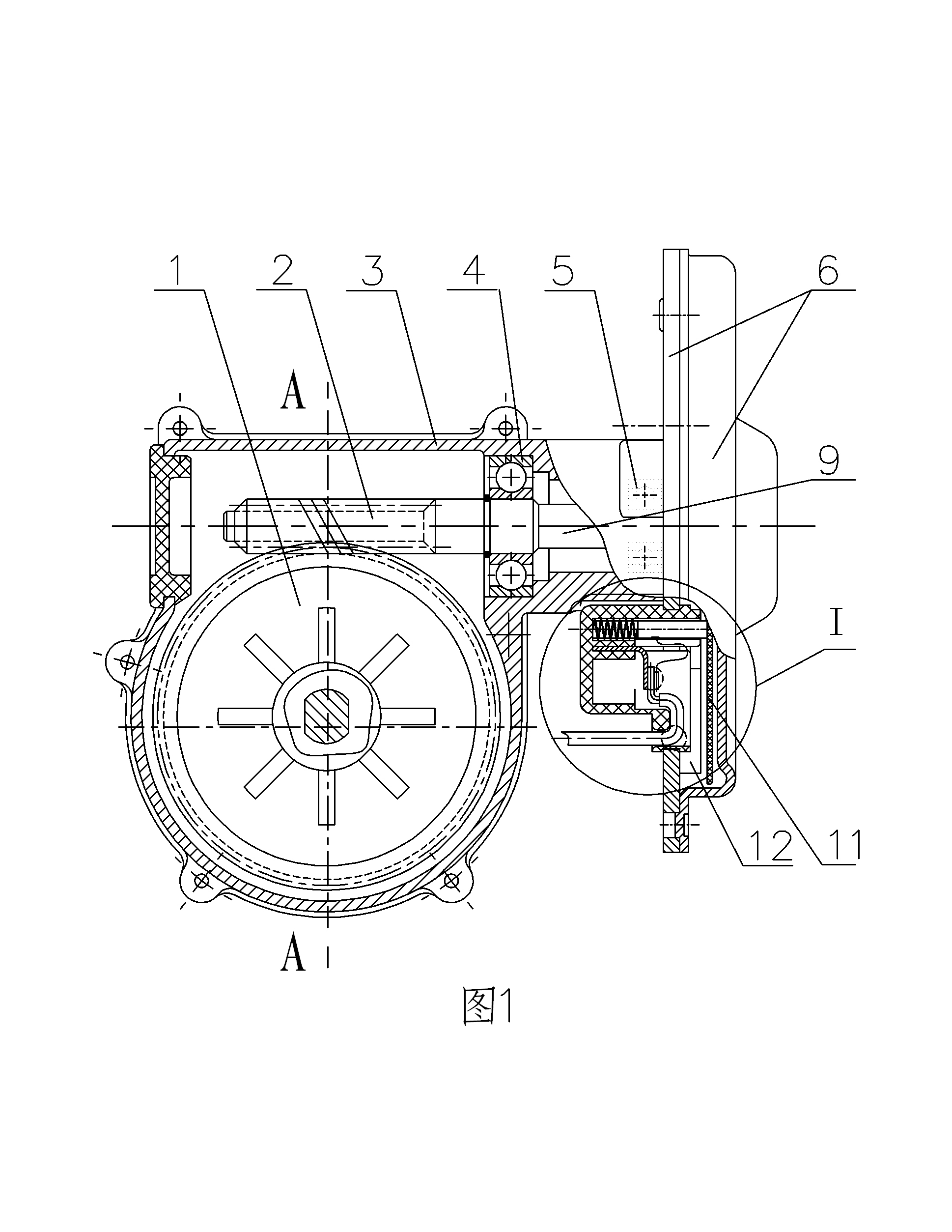
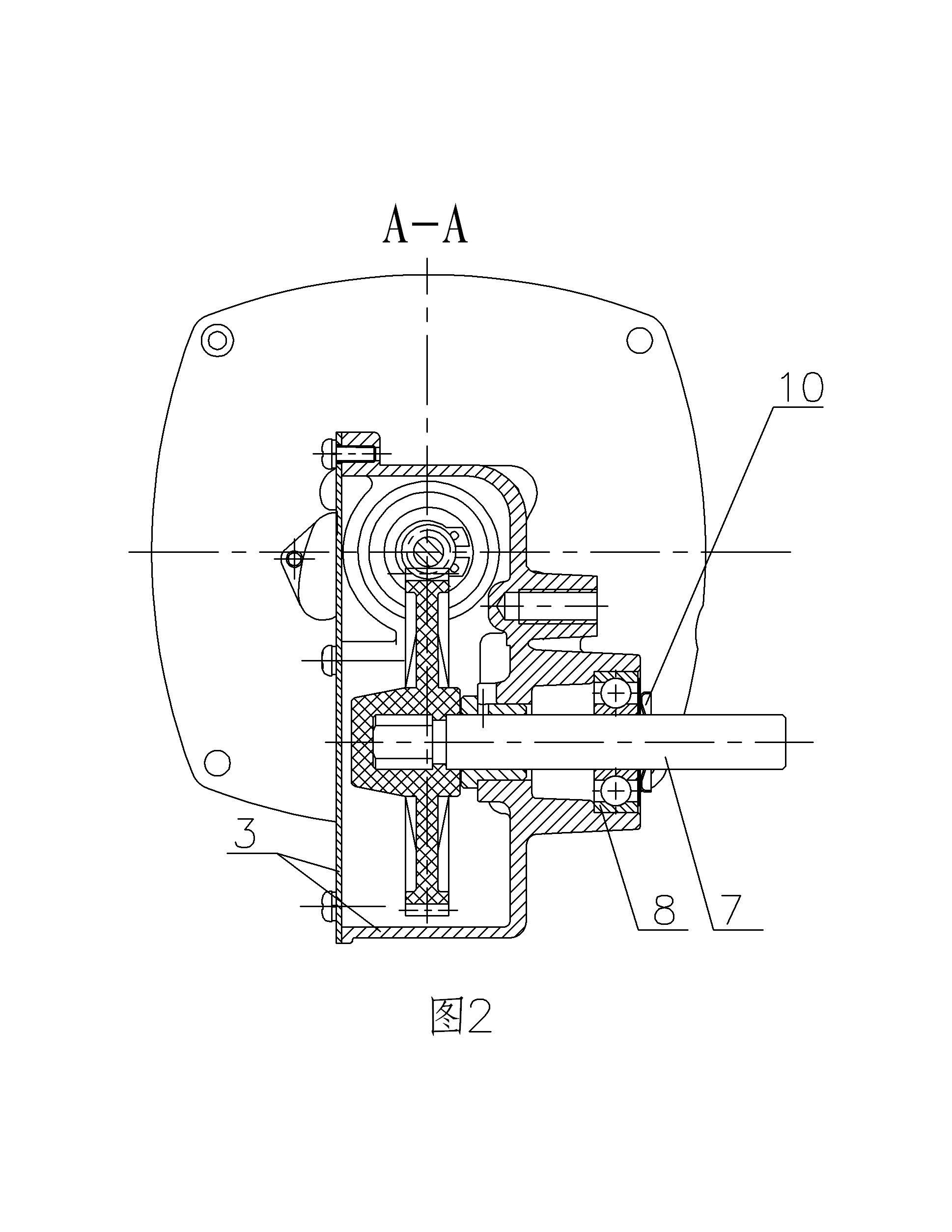
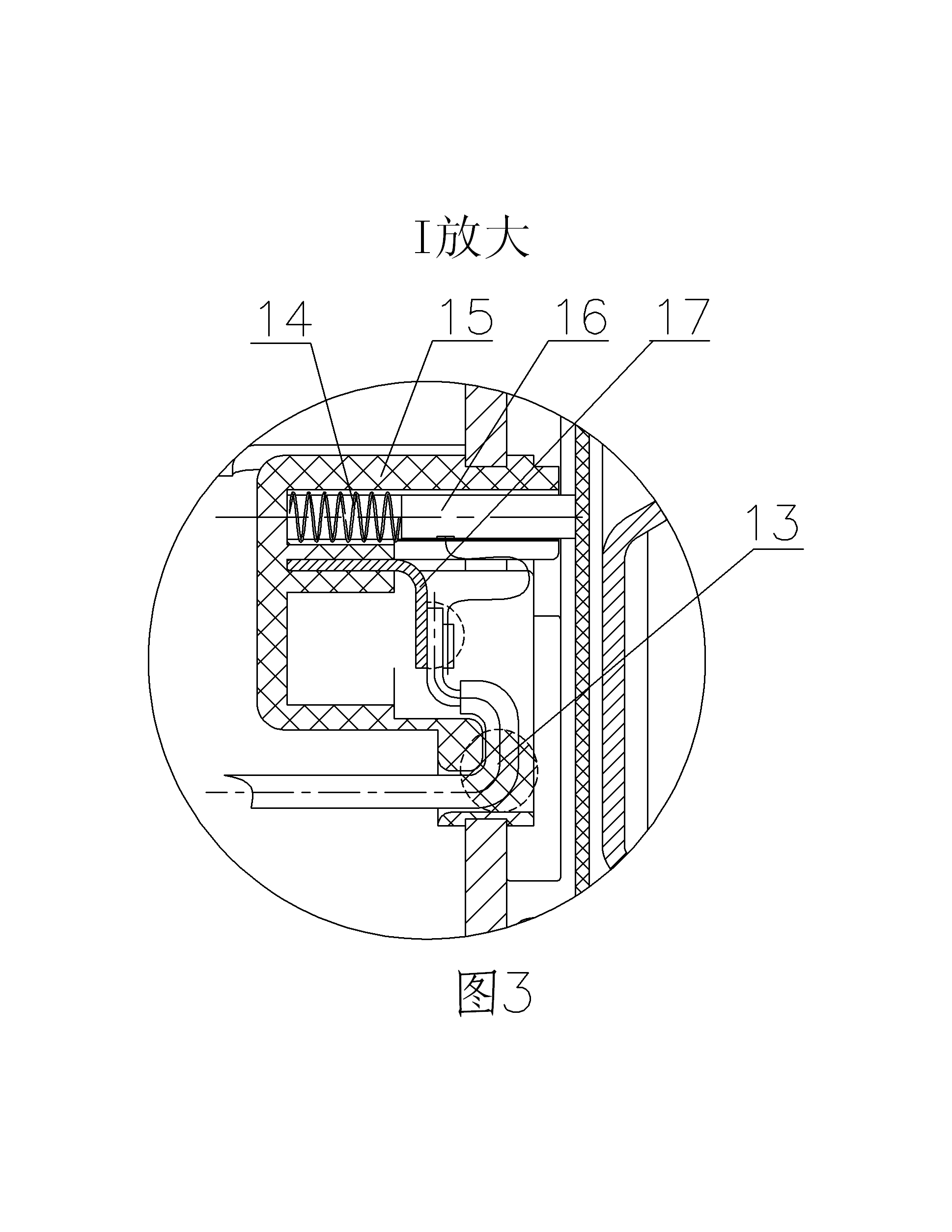
[0033] like Figure 1-Figure 3 Shown is a worm gear reduction type wire feeding motor equipment provided by the present invention, which includes a motor, a power output shaft 7 and a reduction transmission device connected between the power output shaft 7 and the motor output shaft 9 of the motor, and is characterized in that : the motor adopts a flat motor, and the reduction transmission device adopts a worm gear reduction transmission device.

[0034] The worm gear reduction transmission device includes a reduction box body 3 and a worm wheel 1 and a worm 2 assembly that are arranged in the reduction box body 3 for transmission, and the worm wheel 2 is connected to the motor output shaft 9 for transmission, and the motor output shaft 9 It is integrally connected with the worm 2 coaxially, and is connected with the reduction box body 3 through the front support bearing 4 and the rear support bearing 5 in rotational support.

[0035] The power output shaft 7 is connected to th...

Embodiment 2

[0039] like Figure 4 Shown is a wire feeding device provided by the present invention with the above-mentioned worm gear reduction type wire feeding motor device, which includes a frame assembly 18, a bracket assembly 19 and a wire feeding motor device 21 installed on the frame assembly 18 , the wire feeding motor equipment 21 includes a motor, a power output shaft 7 and a deceleration transmission device connected between the power output shaft 7 and the motor output shaft 9 of the motor, wherein the motor adopts a flat motor, and the deceleration The transmission device adopts the worm gear reduction transmission device.

[0040] The above-mentioned wire feeding device may be provided with a disk shaft assembly 20 or not provided with a disk shaft assembly 20 as required. In addition, the shapes and combinations of the parts such as the frame assembly 18, the bracket assembly 19, the disk shaft assembly 20 and the wire feeding motor equipment 21 of the wire feeding device ...

Embodiment 3

[0045] like Figure 5 Shown is a welding system provided by the present invention with the above-mentioned wire feeding device, which includes a wire feeding device 22, a welding power supply device 23, a control device 24, and a welding torch 25; the wire feeding device includes a frame assembly 18 and an installation The bracket assembly 19 and the wire feeding motor equipment 21 on the frame assembly 18; the wire feeding motor equipment 21 includes a motor, a power output shaft 7 and a speed reducer connected between the power output shaft 7 and the motor output shaft 9 of the motor Transmission device; one output electrode of the welding power supply device 23 is connected to the bracket assembly 19 through a welding power supply output cable 26 to provide a welding power supply, and the other output electrode is used to connect with the workpiece to be welded through another welding power supply output cable 27 The welding torch 25 is connected to the welding wire 29 deli...


PUM


Abstract

The invention relates to worm-gear speed-reducing wire-feeding motor equipment as well as a wire feeding device provided with the same and a welding system provided with the same. The wire-feeding motor equipment comprises a motor, a power output shaft and a speed-reducing transmission device connected between the power output shaft and the motor output shaft of the motor, wherein the motor is a flat motor and the speed-reducing transmission device is a worm-gear speed-reducing transmission device. The wire feeding device provided with the wire-feeding motor equipment further comprises a frame assembly and a support assembly. The welding system provided with the wire feeding device comprises welding power source equipment, a control device and a welding gun, wherein the control device comprises a voltage and / or current value detection module, a speed control module, voltage and / or current fluctuation detection equipment and a wire drawing and feeding control module. According to the invention, not only can the service life of the wire-feeding motor equipment and the service life of the wire feeding device be prolonged, but also the dynamic response speed of the wire-feeding motor equipment and the dynamic response speed of the wire feeding device are greatly improved, so that the dynamic response speed of the welding system, which meets the requirements of low spattering and even no spattering, is achieved during welding.

Description

technical field [0001] The invention relates to a worm gear reduction type wire feeding motor equipment, a wire feeding device and a welding system, which are mainly used for welding wire feeding. Background technique [0002] The existing wire feeding motors and wire feeding devices for welding wire feeding mainly have the following disadvantages: (1) The motor adopts a long cylindrical brushed permanent magnet DC motor, which not only slows the dynamic response speed, but also shortens the life of the wire feeding motor products. Seriously affected by the short life of the long cylindrical brushed permanent magnet DC motor; (2) The output end bearing structure of the deceleration transmission device is unreasonable, and it is very easy to cause the inner ring or outer ring of the output end bearing to match the matching parts in practical applications. Relative sliding occurs on the surface of the bearing, which causes the rolling bearing function of the output bearing to...

Claims


Application Information

Patent Timeline
Patent Type & Authority Applications(China)
IPC IPC(8): H02K7/10B23K9/00B23K9/133B23K9/10
Inventor 郑美波
Owner 贝姆勒精密机电(厦门)有限公司
Learn More