Eureka AIR delivers breakthrough ideas for toughest innovation challenges, trusted by R&D personnel around the world.

Design method for direct current (DC) filter in high voltage DC transmission project

A high-voltage DC transmission and DC filter technology, which can reduce harmonics/ripples and other directions when applied to DC circuits, can solve problems such as difficulty in adjusting filter parameters, and achieve the effects of convenient filter parameters, clear physical concepts, and improved efficiency

Inactive Publication Date: 2011-05-25
ZHEJIANG UNIV
View PDF2 Cites 14 Cited by
  • Summary
  • Abstract
  • Description
  • Claims
  • Application Information

AI Technical Summary

Problems solved by technology

[0005] The traditional three-tuned filter design method uses the three-tuned filter parameter calculation formula derived based on the tuning point filter impedance Z=0, but it is difficult to adjust the filter parameters according to the formula, and in the actual design process, the filter parameters need to be keep adjusting

Method used


Image

  • Design method for direct current (DC) filter in high voltage DC transmission project
  • Design method for direct current (DC) filter in high voltage DC transmission project
  • Design method for direct current (DC) filter in high voltage DC transmission project

Examples


Embodiment 1

[0067] In this embodiment, the correctness of the above equivalent method is verified by comparing the impedance-frequency characteristic curves of a given three-tuned filter and three equivalent single-tuned filters.

[0068] Assume that the type of three-tuned filter to be designed is TT12 / 24 / 36 (tuning times are N 1 =12,N 2 =24,N 3 =36), the main capacitor is chosen as C 1 = 1.2e-6F.

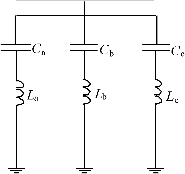
[0069] Order C 0 =C 1 =C 2 =C 1 / 3, then the parameters of the single-tuned filter are determined according to formulas (2) to (4) (considering that the fundamental frequency is 50Hz):

[0070] C a =C b =C c =0.4e-6F

[0071] L a =0.1759H, L b =0.04398H,L c =0.01954H

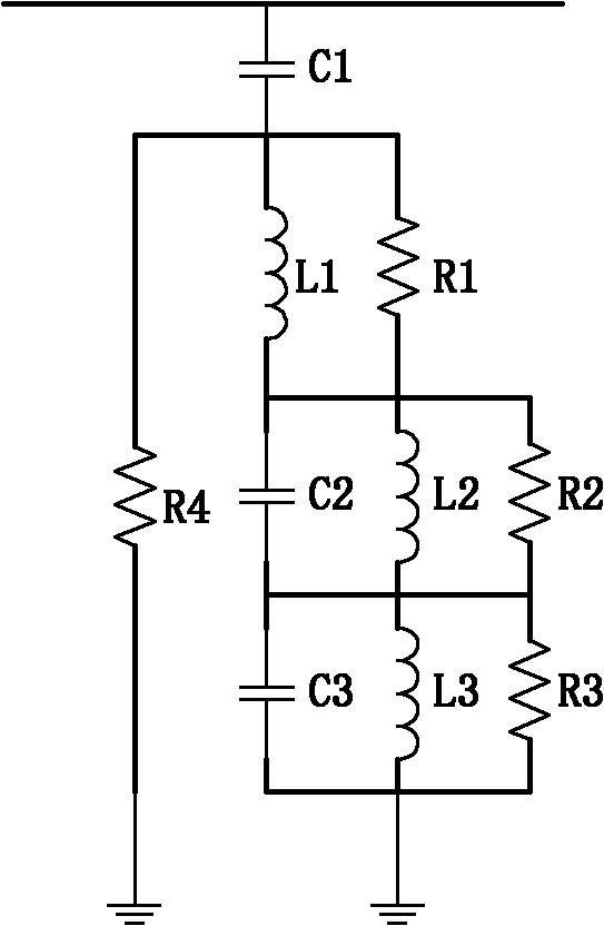
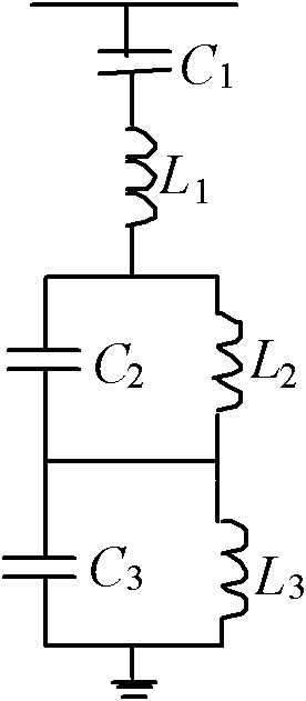
[0072] Then according to equations (13)~(18), the parameters of the three-tuned filter are determined:

[0073] C 2 = 4.40e-6F, C 3 =5.28e-6F

[0074] L 1 =0.01256H,L 2 =0.01167H,L 3 =0.00237H

[0075] The impedance frequency characteristics of the three-tuned filter and three equivalent single-tuned filt...

Embodiment 2

[0077] This embodiment takes a domestic ±800kV double-twelve-pulse DC project in series as an example, and its preliminary relevant parameters are shown in Table 1. The smoothing reactors are arranged separately and installed on the DC pole bus and neutral bus respectively. , each is 150mH. Its performance requirement is that the equivalent interference current Ieq≤2000mA during bipolar operation. Based on the conditions of forward power transmission, bipolar, DC full voltage, DC high resistance and AC voltage on both sides as the rated value, the calculated power transmission level starts from 0.1pu, takes 0.05pu as the step size, and reaches all load levels of 1.25pu Equivalent interference current.

[0078] Table 1 DC Engineering Parameters

[0079]

[0080] The weighted maximum 10th harmonic current when the rated load is delivered without filter is as attached Figure 5 shown. The largest 5th weighted harmonic has been marked in the figure, because the weighting co...


PUM


Abstract

The invention discloses a design method for a DC filter in a high voltage DC transmission project. The design method comprises the following steps of: (1) determining the main capacitance and tuning frequency of the filter according to the system conditions; (2) equalizing the three-tuning filter to 3 single-tuning filters, and calculating the parameters of each single-tuning filter on the restrictive conditions of the main capacitance and tuning frequency of the three-tuning filter; (3) acquiring the parameter of the three-tuning filter based on the parameters of single-tuning filters through an equivalence formula according to the principle of admittance consistency; and (4) performing performance computation for the configured filter, regulating the main capacitance or tuning frequencyof each single-tuning filter if requirements are not met, and then repeating the steps till the requirements are met. The design method is clear in physical concept, convenient in parameter adjustment and high in engineering application value, and can greatly improve the design efficiency of the DC filter.

Description

technical field [0001] The invention relates to the technical field of high-voltage direct current transmission engineering, in particular to a design method for a direct current filter of a high-voltage direct current transmission project. Background technique [0002] Due to the nonlinear characteristics of the converter in the HVDC power transmission system, harmonics will be generated on both sides of the AC and DC when it realizes the conversion of AC and DC. Harmonics on the DC side will be injected into the DC pole line and the DC grounding pole line, disturbing the communication system along the line. Therefore, a DC filter needs to be installed on the DC side of the DC power transmission project in the form of overhead lines to filter out these harmonics. The DC filter is generally located between the pole bus and the pole neutral bus. Considering the symmetry of the two poles of the same converter station, the two poles are usually equipped with the same DC filte...

Claims


Application Information

Patent Timeline
IPC IPC(8): H02J1/02
Inventor 徐政薛英林王峰
Owner ZHEJIANG UNIV
Why Eureka
Eureka Blog
Learn More