DC-DC converter with snubber circuit

A DC-DC, buffer circuit technology, applied in the conversion device for adjusting electrical variables, output power, converting DC power input to DC power output, etc., can solve problems such as damage, prevent damage, reduce impact voltage and noise generation , the effect of high-speed action

Inactive Publication Date: 2014-02-26
SANKEN ELECTRIC CO LTD +1
View PDF6 Cites 0 Cited by
  • Summary
  • Abstract
  • Description
  • Claims
  • Application Information

AI Technical Summary

Problems solved by technology

[0017] However, even if the recovery loss of the diodes D3 and D4 can be suppressed, resonance occurs between the reactors La and Lb added to suppress the recovery loss and the capacitance of the depletion layers of the diodes D3 and D4 that are turned off and in the reverse blocking state. , because of this resonance will generate surge voltage and ringing
Therefore, noise that destroys components such as switches will be generated

Method used


Image

  • DC-DC converter with snubber circuit
  • DC-DC converter with snubber circuit
  • DC-DC converter with snubber circuit

Examples


Embodiment 1

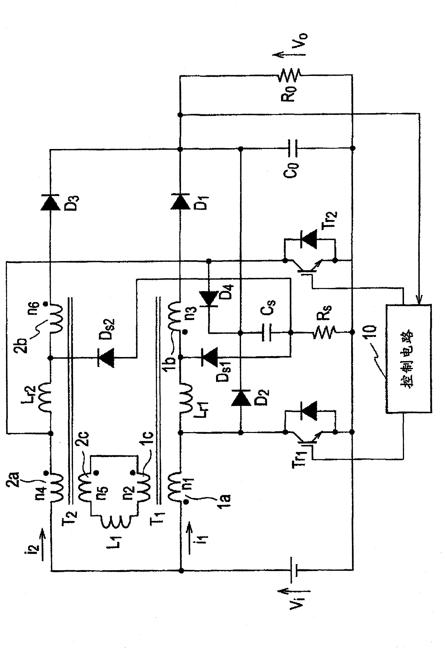
[0043] figure 2 It is a circuit configuration diagram showing the DC-DC converter with the snubber circuit of the first embodiment. figure 2 The shown DC-DC converter with a snubber circuit is composed of a multi-phase transformer-linked (Trans-Linked) step-up chopper circuit.

[0044] A DC-DC converter with a snubber circuit includes a DC power supply Vi, a transformer T1 (first transformer), a transformer T2 (second transformer), a reactor Lr1 (first reactor), a reactor Lr2 (second reactor), Reactor L1 (third reactor), switch Tr1 (first switch), switch Tr2 (second switch), diode D1, diode D2, diode D3, diode D4, snubber diode Ds1 (first snubber diode), snubber diode Ds2 (second snubber diode), snubber resistor Rs, snubber capacitor Cs, smoothing capacitor Co, and control circuit 10 .

[0045] The transformer T1 has a primary coil 1a (number of turns n1), a booster coil 1b (number of turns n3), and a secondary coil 1c (number of turns n2) electromagnetically coupled to th...

Embodiment 2

[0069] Figure 13 It is a circuit configuration diagram showing a DC-DC converter with a snubber circuit according to the second embodiment. In Embodiment 1, the reactor Lr1 is connected in series to the lifting coil 1b, and the reactor Lr2 is connected in series to the lifting coil 2b. Embodiment 2 is characterized in that the reactor Lr1 is connected in series to the switch Tr1, and the reactor Lr2 is connected in series to the switch Tr2.

[0070] The structure of the snubber circuit composed of snubber capacitor Cs, snubber resistor Rs, snubber diode Ds1, and snubber diode Ds2 is due to the figure 2 The structure of the illustrated embodiment 1 is the same, so the explanation is omitted.

[0071] Here, the operation and effect of the DC-DC converter having a snubber circuit when the reactors Lr1 and Lr2 are connected in series to the switches Tr1 and Tr2 will be described.

[0072] First, the switch Tr1 is turned on according to a gate signal from the switch Tr1 of the...


PUM


Abstract

In order to achieve an object to reduce a surge voltage and suppress noise generation, the present invention provides a DC-DC converter with a snubber circuit, which boosts a voltage Vi of a DC power supply. The snubber circuit includes: a series circuit connected to both ends of a smoothing capacitor Co and including a snubber capacitor Cs and a snubber resistor Rs; a snubber diode Ds1 connected to a node at which the snubber capacitor Cs and the snubber resistor Rs are connected, and to a node at which a reactor Lr1 and an additional winding 1b of a transformer T1 are connected; and a snubber diode Ds2 connected to the node at which the snubber capacitor Cs and the snubber resistor Rs are connected, and to a node at which a reactor Lr2 and an additional winding 2b of a transformer T2 are connected.

Description

technical field [0001] The invention relates to a DC-DC converter with a snubber circuit composed of a step-up chopper circuit, in particular to a DC-DC converter with a snubber circuit suitable for electric vehicles. Background technique [0002] figure 1 It is a circuit configuration diagram of a conventional DC-DC converter described in Japanese Patent Application Laid-Open No. 2006-262601. The step-up DC-DC converter includes a DC power supply Vdc1 , a transformer T3 , a transformer T4 , a reactor L3 , a switch Q1 , a switch Q2 , a diode D3 , a diode D4 , a smoothing capacitor C1 , and a control circuit 100 . [0003] The transformer T3 has: a primary coil 5a (number of turns np), a booster coil 5b (number of turns np1) connected in series with the primary coil 5a, and a secondary coil 5c (number of turns ns) electromagnetically coupled to the primary coil 5a and the booster coil 5b. ). The transformer T4 has the same structure as the transformer T3, and has a primary...

Claims


Application Information

Patent Timeline
Patent Type & Authority Patents(China)
IPC IPC(8): H02M3/155
CPCH02M3/1584H02M2001/348H02M1/34H02M1/348Y02B70/10
Inventor 足助英树高野秀治鹤谷守山本真义川岛崇广船曳繁之
Owner SANKEN ELECTRIC CO LTD
Why Eureka
Try Eureka