
Amplitude shift keying (ASK)/on-off keying (OOK) radio frequency (RF) receiving circuit

A radio frequency receiving and circuit technology, applied in the direction of electrical components, transmission systems, AM carrier systems, etc., can solve the problems of unfavorable cost, reduction, large chip area and power consumption, etc., and achieve simple structure, strong anti-interference ability, small chip area effect

Inactive Publication Date: 2011-05-18
HANGZHOU SILAN MICROELECTRONICS
View PDF3 Cites 18 Cited by
  • Summary
  • Abstract
  • Description
  • Claims
  • Application Information

AI Technical Summary

Problems solved by technology

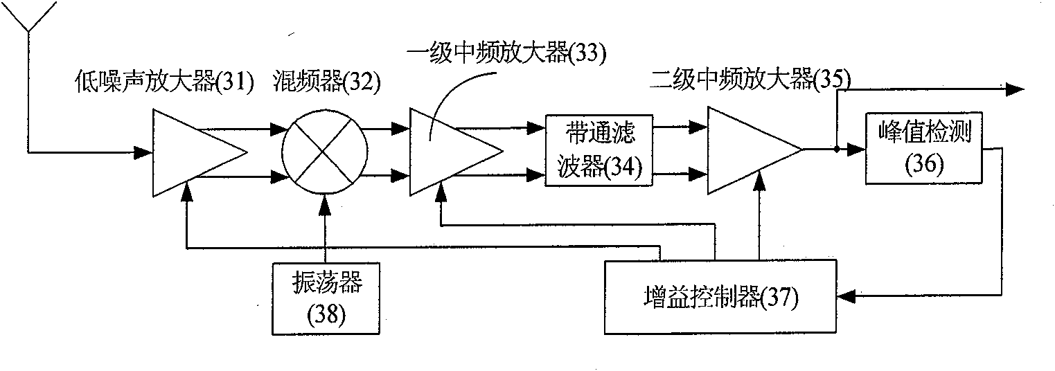
The above methods are widely used, but the digital method uses an analog-to-digital converter, which occupies a large chip area and power consumption, which is not conducive to cost reduction; and the analog method is used to ensure that the sensitivity of the receiving circuit is not affected. Loss, generally only controls the gain of the intermediate frequency amplifier or mixer, and if you want to increase the adjustment of the gain of the low noise amplifier to obtain a higher dynamic range, you generally need to use a complex gain controller (gain controller) to control the feedback signal After the operation is performed, the gain of each unit is controlled separately (such as image 3 shown)

Method used


Image

  • Amplitude shift keying (ASK)/on-off keying (OOK) radio frequency (RF) receiving circuit
  • Amplitude shift keying (ASK)/on-off keying (OOK) radio frequency (RF) receiving circuit
  • Amplitude shift keying (ASK)/on-off keying (OOK) radio frequency (RF) receiving circuit

Examples


Embodiment Construction

[0023] The content of the present invention will be further described below in conjunction with the accompanying drawings.

[0024] ASK / OOK RF receiving circuit, such as Figure 4 As shown, including: low noise amplifier (41), oscillator (50), mixer (42), primary intermediate frequency amplifier (43), intermediate frequency bandpass filter (44), secondary intermediate frequency amplifier (45), Peak detection module (46), comparator (47), charge pump (48), capacitor, described low noise amplifier (41) common with the local oscillator that described oscillator (50) produces after amplifying the signal that antenna receives Input mixer (42), described mixer (42) reduces the frequency of low noise amplifier (41) output to intermediate frequency, and the intermediate frequency signal of mixer (42) output is amplified (43) through one-stage intermediate frequency amplifier again , the intermediate frequency bandpass filter (44) and the secondary intermediate frequency amplifier (45...


PUM


Abstract

The invention provides an amplitude shift keying (ASK) / on-off keying (OOK) radio frequency (RF) receiving circuit. The receiving circuit is characterized in that after a low noise amplifier amplifies the received signal, the amplified received signal and local oscillation generated by an oscillator are jointly input into a mixer; the mixer reduces the frequency output by the low noise amplifier to intermediate frequency; the intermediate frequency signal output by the mixer is demodulated and output by a peak detection module after being amplified by a primary intermediate frequency amplifier, filtered by an intermediate frequency bandpass filter and amplified by a secondary intermediate frequency amplifier; a charge pump is driven after the peak detection output potential is compared with the fourth reference potential Vref4; the charge pump charges and discharges a capacitor to obtain gain control signals; the gain control signals are fed back to the low noise amplifier, the primary intermediate frequency amplifier and the secondary intermediate frequency amplifier to form an automatic gain control loop; and the low noise amplifier, the primary intermediate frequency amplifier and the secondary intermediate frequency amplifier respectively input the first, second and third reference potentials. The receiving circuit solves the problem of blocking during close range remote control, and meanwhile, the antijamming capability of the receiving circuit is improved and the cost is saved.

Description

technical field [0001] The invention relates to the field of signal and information processing, in particular to radio frequency receiving technology. Background technique [0002] Traditional remote control circuits, such as toy car remote control circuits, door and window remote control circuits, etc., mostly use ASK / OOK modulation, and their receiving circuits generally have two implementation methods: super regenerative circuit and super heterodyne circuit. The super regenerative circuit is widely used due to its low cost, simple circuit and high sensitivity. However, compared with the super heterodyne structure, it has problems such as difficulty in integration and weak anti-interference ability. [0003] The structure of a current superheterodyne radio frequency receiving circuit is as follows: figure 1 As shown, the signal received by the antenna is amplified by the low noise amplifier (11) and then down-converted to the intermediate frequency by the mixer (12) toget...

Claims


Application Information

Patent Timeline
IPC IPC(8): H04B1/16H04L27/06
Inventor 胡铁刚潘华兵蔡康康
Owner HANGZHOU SILAN MICROELECTRONICS
Learn More