


Quick Research
Generate reliable direction feasibility study reports for your R&D in just a few steps.

Technical Q&A
Discover and master advanced knowledge NOW. Basics, ideas, possibilities, all at once.

Find Solutions
As an expert in R&D theories, this can generate solutions to your technical problems instantly.

Evaluate Feasibility
Analyze your overall solution with one click, know your potential R&D risks in advance.

Monitor Landscape
Get weekly tech updates, stay abreast of the latest tech innovations and key insights.
Display device, method of driving the same, and electronic unit
A display device and drive circuit technology, applied to static indicators, instruments, etc., can solve problems such as changes in luminous brightness levels and deterioration of screen uniformity, and achieve the effects of gentle tilt, cost reduction, and high picture quality
- Summary
- Abstract
- Description
- Claims
- Application Information
AI Technical Summary
Problems solved by technology
Method used
Image

Examples
no. 1 example
[0080] 1. Display driver operation
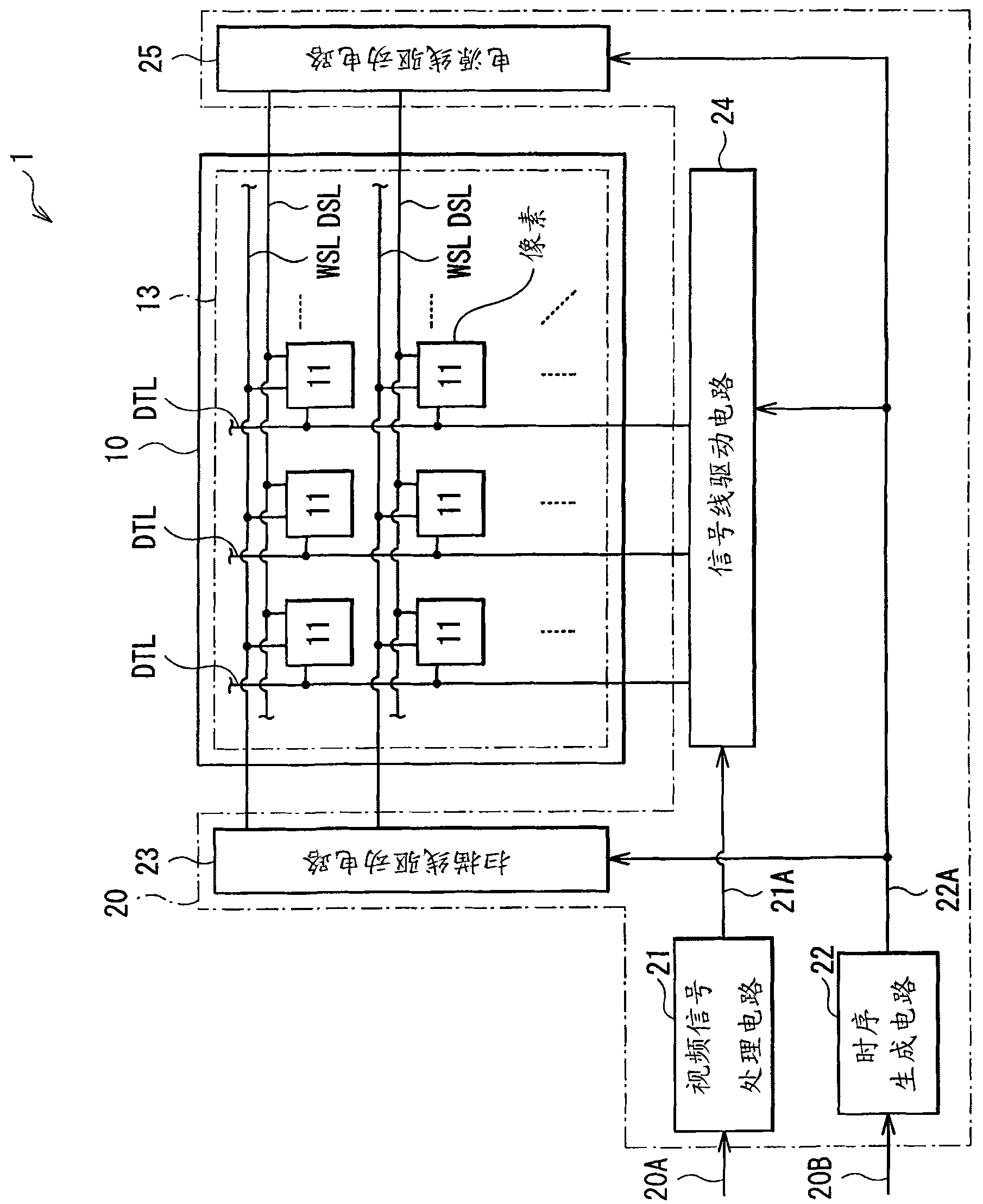
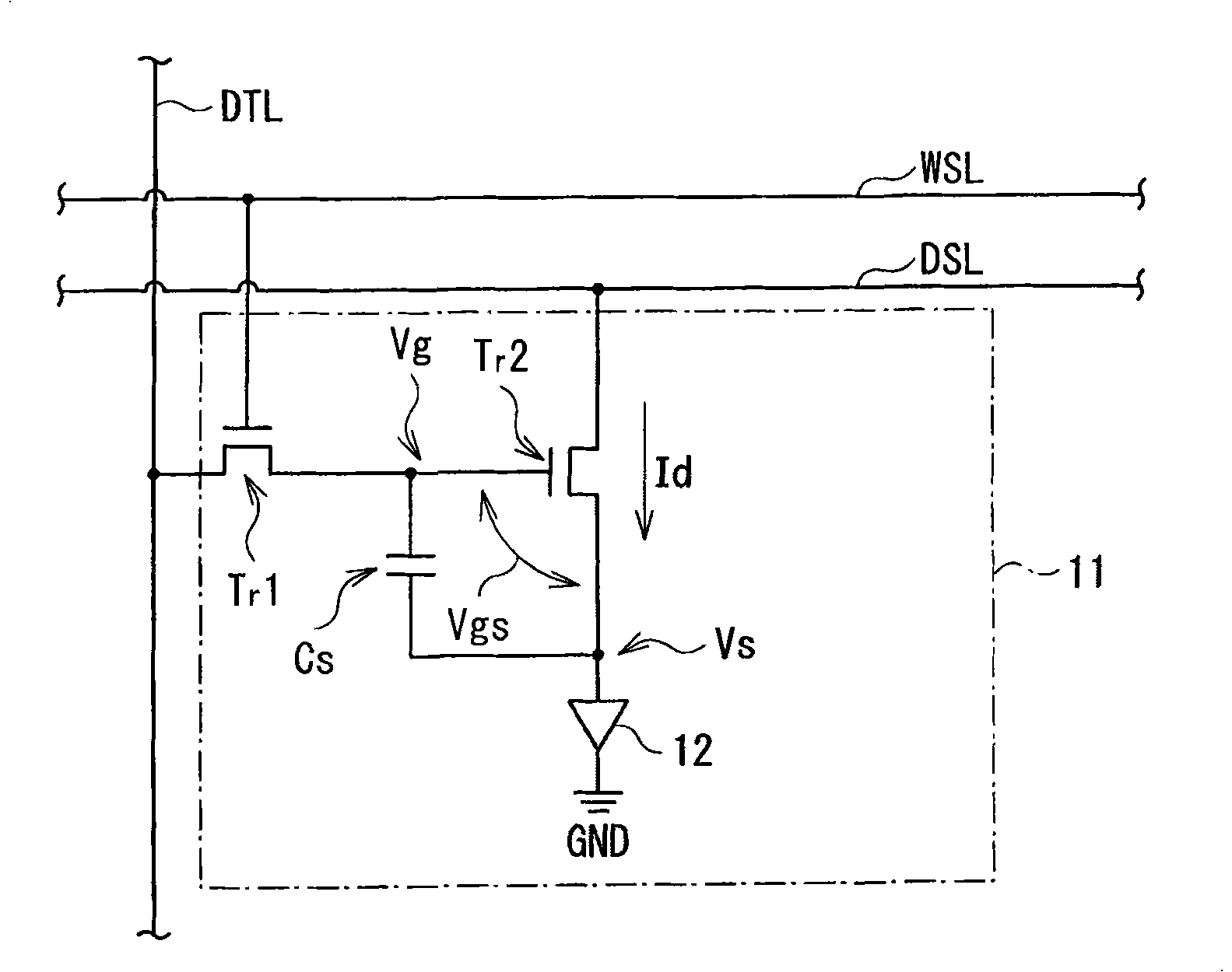
[0081] In display device 1, such as figure 1 and 2 As shown, the driving circuit 20 performs display driving on the pixels 11 in the display panel 10 (pixel array 13 ) based on the video signal 20A and the synchronization signal 20B. By display driving, a driving current is injected into the organic EL element 12 in each pixel 11, holes and electrons are recombined, and light emission occurs. The generated light is taken outside, and an image is displayed on the display panel 10 .
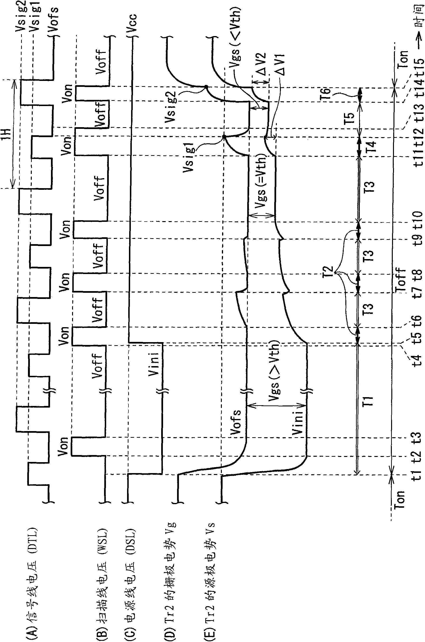
[0082] refer to image 3 Parts (A) to (E) of , the detailed display driving operation in this embodiment will be described. image 3 Sections (A) to (E) in are examples of various timing waveforms. image 3 Parts (A) to (C) in , respectively illustrate signal pulses applied to the signal line DTL, the scanning line WSL, and the power supply line DSL. image 3 Parts (D) and (E) in (E) respectively illustrate the waveforms of the gate potential Vg and the so...
no. 2 example
[0133] 1. Display driver operation
[0134] Also in the second embodiment, in a manner similar to the first embodiment, as figure 1 and 2As shown, in the display device 1 , the driving circuit 20 performs display driving on the pixels 11 in the display panel 10 based on the video signal 20A and the synchronization signal 20B. A drive current is injected into the organic EL element 12 in each pixel 11, holes and electrons recombine, and light emission occurs. The generated light is taken outside, and an image is displayed. In the following, the display driving operation in this embodiment will be described in detail.
[0135] Figure 9 Parts (A) to (E) in are various timing waveforms of the embodiment. Figure 9 Parts (A), (B) and (C) in , illustrate signal pulses applied to the signal line DTL, the scan line WSL, and the power supply line DSL, respectively. Figure 9 Parts (D) and (E) in (E) respectively illustrate the waveforms of the gate potential Vg and the source po...
no. 3 example
[0165] 1. Display driver operation
[0166] Also in the third embodiment, in a manner similar to the first embodiment, as figure 1 and 2 As shown, in the display device 1 , the driving circuit 20 performs display driving on the pixels 11 in the display panel 10 based on the video signal 20A and the synchronization signal 20B. A drive current is injected into the organic EL element 12 in each pixel 11, resulting in light emission. The generated light is taken outside, and an image is displayed. In the following, the display driving operation in this embodiment will be described in detail.
[0167] Figure 12 Parts (A) to (E) in are various timing waveforms of the embodiment. Figure 12 Parts (A), (B) and (C) in , illustrate signal pulses applied to the signal line DTL, the scan line WSL, and the power supply line DSL, respectively. Figure 12 Parts (D) and (E) in (E) respectively illustrate the waveforms of the gate potential Vg and the source potential Vs in the drive tr...
PUM
 Abstract
Description
Claims
Application Information
 - R&D Engineer
- R&D Manager
- IP Professional
- Industry Leading Data Capabilities
- Powerful AI technology
- Patent DNA Extraction
Browse by: Latest US Patents, China's latest patents, Technical Efficacy Thesaurus, Application Domain, Technology Topic, Popular Technical Reports.
© 2024 PatSnap. All rights reserved.Legal|Privacy policy|Modern Slavery Act Transparency Statement|Sitemap|About US| Contact US: help@patsnap.com