
Pressure vessel having improved sealing arrangement

A technology for pressure vessels and tubular components, which can be applied to pressure vessels, outer walls of vessel structures, manufacturing of vessel structures, etc., and can solve problems such as damage to the sealing performance of O-rings

Inactive Publication Date: 2011-05-18
YACHIYO IND CO LTD
View PDF9 Cites 33 Cited by
  • Summary
  • Abstract
  • Description
  • Claims
  • Application Information

AI Technical Summary

Problems solved by technology

However, since the resin liner deforms in a more pronounced manner than the mouth when the inside of the resin liner is pressurized, the sealing performance of the O-ring will be impaired if the deformation of the resin liner is large

Method used


Image

  • Pressure vessel having improved sealing arrangement
  • Pressure vessel having improved sealing arrangement
  • Pressure vessel having improved sealing arrangement

Examples


Embodiment Construction

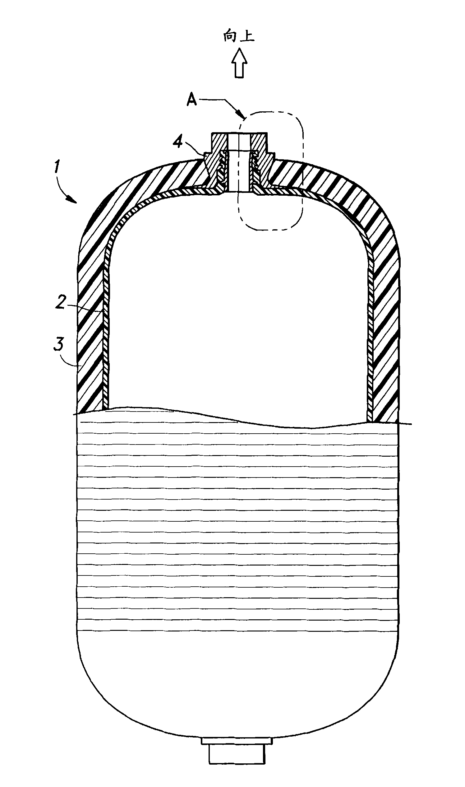
[0020] figure 1 The main parts of a pressure vessel 1 embodying the invention are shown. The pressure vessel 1 includes a resin liner 2 having a cylindrical body portion and a pair of hemispherical axial end portions, a fiber-reinforced resin layer 3 surrounding the outer surface of the resin liner 2 , and fitted to the axial end portions provided on the pressure vessel 1 One of the openings of the mouth4.

[0021] The illustrated pressure vessel 1 can be used in any desired orientation, however, for the purposes of the following description, it is assumed that the pressure vessel 1 is placed in a vertical position with the mouth 4 on top, as shown in the figures.

[0022] The resin liner 2 is made of a material suitable for contacting the gas or liquid to be contained in the pressure vessel 1, which can be selected from various plastic materials such as polyethylene (PE), high-density polyethylene (HDPE), polyamide , polyketone, and polyphenylene sulfide (PPS), depending o...


PUM


Abstract

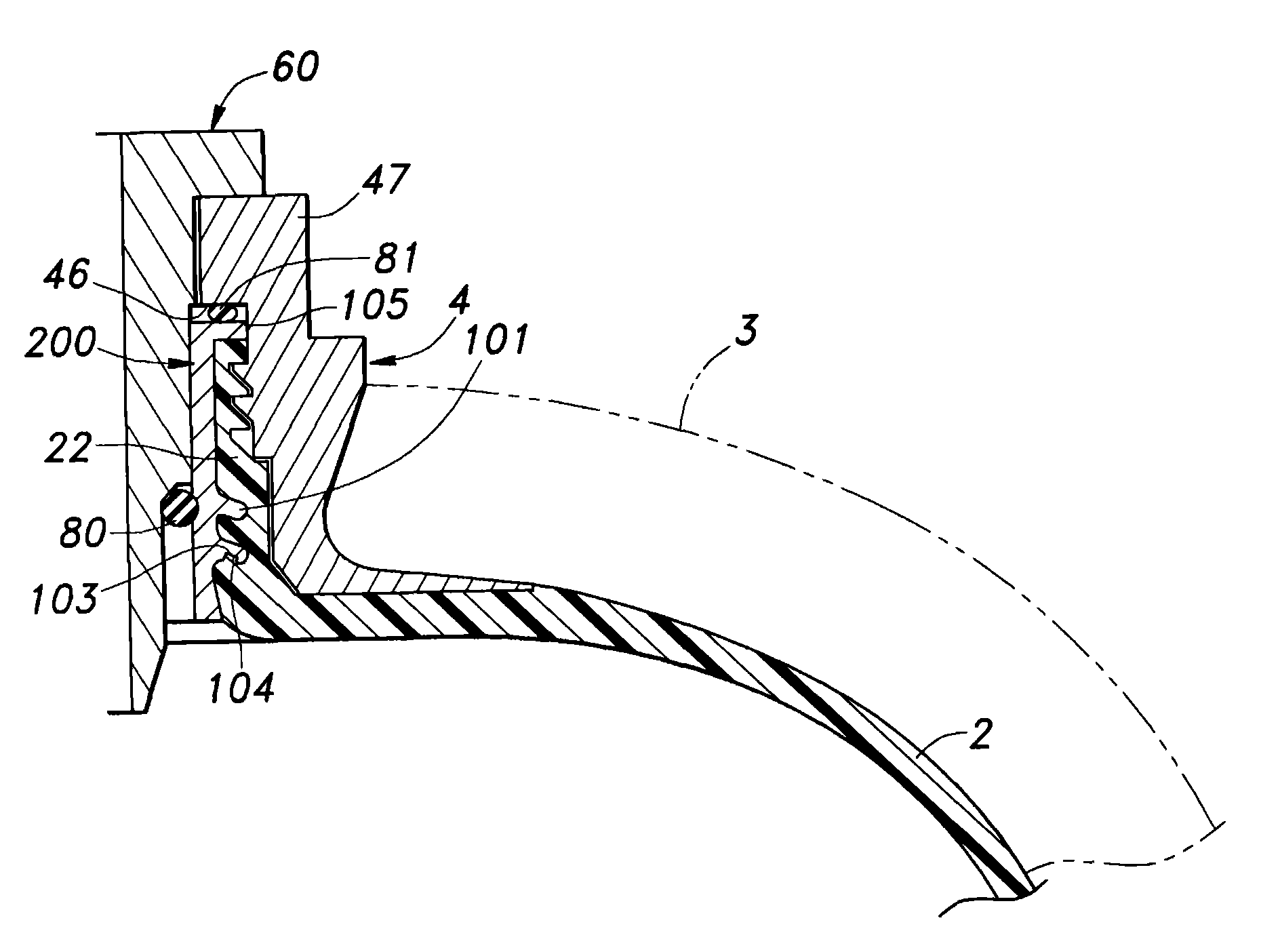
In a pressure vessel (1) comprising a resin liner (2) provided with a tubular extension (22) defining a through hole therein for receiving and expelling the gas or liquid, a tubular member (100, 200, 300) fitted in the through hole of the tubular extension, a mouthpiece (4) threaded into the tubular extension, a fiber reinforced resin layer (3) placed around an outer surface of the resin liner, and a valve (60) fitted into the central bore of the tubular member, the valve include a section (62) having a smaller outer diameter than an opposing inner circumferential surface of the tubular member defining a gap between the valve and tubular member, and a resilient seal member (80) is placed in the gap. The tubular member is made of a material such as metallic material which is stiffer than the resin liner. Thereby, the resilient seal member is interposed between the tubular member and valve which are both highly stiff or free from deformation when the interior of the pressure vessel is placed under various pressure conditions so that the sealing performance of the resilient seal member can be ensured under all pressure conditions.

Description

technical field [0001] The present invention relates to a pressure vessel with an improved sealing structure, especially a pressure vessel having an improved sealing structure suitable for storing pressurized gas such as pressurized natural gas (CNG) under high pressure. Background technique [0002] CNG is considered a cleaner energy source that helps avoid global warming, and is expected to be more widely used as a vehicle fuel in place of conventional gasoline. However, gases are less dense than liquids or solids and thus require a high degree of compression to be stored in the limited space available in motor vehicles and the like. To store compressed gases, pressure vessels capable of withstanding high pressures are required. Steel and aluminum are typical materials used to manufacture CNG pressure vessels. Metal pressure vessels have the advantage of high mechanical strength and proven high reliability, however, the disadvantage of being heavy. Thus, heavy metal pre...

Claims


Application Information

Patent Timeline
Patent Type & Authority Applications(China)
IPC IPC(8): F16J12/00
CPCF17C2260/011F17C2203/0665F17C2203/0619F17C2205/0305F17C2201/0109F17C2209/234F17C2209/2127F17C2209/2154F17C2203/067F17C2205/0382F17C2209/227F17C2223/036F17C2203/0668F17C2201/0128F17C2221/033F17C2260/012F17C2209/221F17C2201/0147F17C1/16F17C2223/0123F17C2203/066F17C2270/0168
Inventor 谷龙志渡边良浩中村晃之佐藤庄司
Owner YACHIYO IND CO LTD
Learn More