Hydraulic excitation system of tamping device

A hydraulic and vibration excitation technology, applied in the directions of roads, tracks, ballast layers, etc., can solve the problems that the vibration frequency cannot be adjusted steplessly, and the hydraulic vibration excitation system cannot be used, so as to achieve continuous control of large flow, improve life, and ensure The effect of stability

Inactive Publication Date: 2012-04-18
ZHEJIANG UNIV
View PDF2 Cites 1 Cited by
  • Summary
  • Abstract
  • Description
  • Claims
  • Application Information

AI Technical Summary

Problems solved by technology

But this tamping device cannot use the existing hydraulic vibration excitation system
[0005] The excitation system of the tamping device of the existing tamping vehicle uses a motor to achieve vibration, and the vibration frequency cannot be adjusted steplessly

Method used


Image

  • Hydraulic excitation system of tamping device
  • Hydraulic excitation system of tamping device
  • Hydraulic excitation system of tamping device

Examples


Embodiment Construction

[0019] The present invention will be further described below in conjunction with drawings and embodiments.

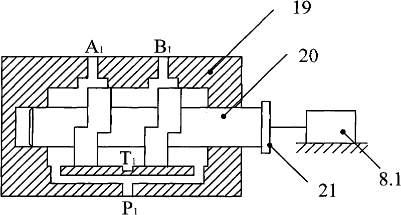
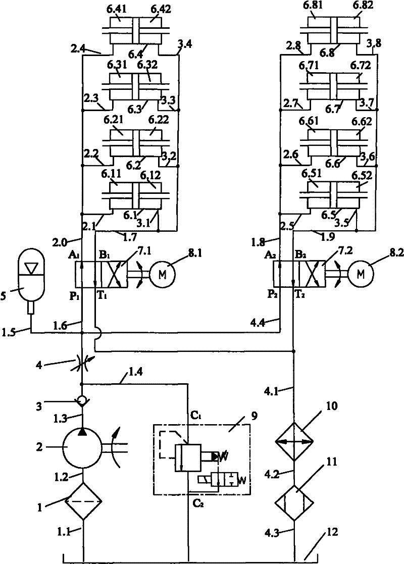
[0020] like figure 1 As shown, the input end of hydraulic pump 2 of the present invention communicates with oil suction filter 1 through pipeline 1.2; Liquid inlet C of electromagnetic overflow valve 9 1 connected, and the outlet of the one-way valve 3 is connected with the inlet of the throttle valve 4; the outlet of the throttle valve 4 is connected to the oil supply pressure oil port P of the spool rotary four-way high-speed reversing valve 7.1 through the pipeline 1.6 1 The other outlet of the throttle valve 4 is connected to the oil supply pressure oil port P of the spool rotary four-way high-speed reversing valve 7.2 in another execution and control unit through the pipeline 4.4 2 connected. As a preferred solution of the present invention, at the oil supply pressure oil port P of the spool rotary four-way high-speed reversing valve 1 ,P 2 An accumulator 5 is...


PUM


Abstract

The invention discloses a hydraulic excitation system of a tamping device. The hydraulic excitation system comprises more than one execution and control units, wherein, each execution and control unit comprises more than one pair of symmetric hydraulic cylinders; first operating cavities of the symmetric hydraulic cylinders are communicated via oil tubes, and second operating cavities of the symmetric hydraulic cylinders are communicated via oil tubes; one pressure oil inlet of an operating cavity of a de-execution mechanism of each four-way high-speed change valve with a rotary valve core iscommunicated with the first operating cavities of the symmetric hydraulic cylinders, and the other pressure oil inlet of the operating cavity is communicated with the second operating cavities; a supply pressure oil inlet of each four-way high-speed change valve with a rotary valve core is communicated with outlets of a throttle valve, and an oil return opening of each four-way high-speed change valve with a rotary valve core is communicated with a cooler; and the cooler is communicated with an air drier; and an outlet of a check valve is respectively communicated with an inlet of the throttle valve and an inlet of an electromagnetic relief valve, an inlet of the check valve is communicated with the output end of a hydraulic pump, and the input end of the hydraulic pump is communicated with an oil suction filter. By utilizing the hydraulic excitation system, continuous reversing control and stepless control of reversing frequency are realized under a high flow condition.

Description

technical field [0001] The invention relates to the technical field of a railway tamping device and a fluid pressure actuator, in particular to a hydraulic vibration excitation system of a tamping device. Background technique [0002] The tamping device is a track maintenance equipment specially used for tamping railway track ballast. Compared with traditional electric tamping machines and small hydraulic tamping machines, the tamping device has many advantages such as safe, stable, fast and low labor intensity. At present, the tamping device has achieved diversified structural forms, unique excitation methods, and high operating efficiency, and has been widely used in domestic line maintenance operations, showing unique advantages. With the vigorous development of my country's railway construction and social progress, tamping devices will inevitably become the mainstream. [0003] The operating characteristics of the tamping device require that the tamping device must rea...

Claims


Application Information

Patent Timeline
Patent Type & Authority Patents(China)
IPC IPC(8): E01B27/20
Inventor 龚国芳刘毅闵超庆杨学兰杨华勇
Owner ZHEJIANG UNIV
Why Eureka
Try Eureka