Combined rotor power machine

A composite rotor and power machine technology, applied to rotary piston engines, rotary or oscillating piston engines, machines/engines, etc., can solve the problems of difficult processing and manufacturing, complex structure, low efficiency, etc., and achieve simple structure and high operating efficiency , a wide range of effects

Active Publication Date: 2014-03-19
白明
View PDF6 Cites 1 Cited by
  • Summary
  • Abstract
  • Description
  • Claims
  • Application Information

AI Technical Summary

Problems solved by technology

[0003] Purpose of the invention: The present invention provides a compound rotor power machine, the purpose of which is to solve the problems of complex structure, difficult manufacturing and low efficiency of the previous equipment

Method used


Image

  • Combined rotor power machine
  • Combined rotor power machine

Examples


specific Embodiment approach

[0016] detailed description: Below in conjunction with accompanying drawing, the present invention will be further described:

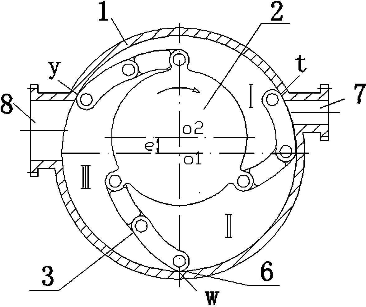
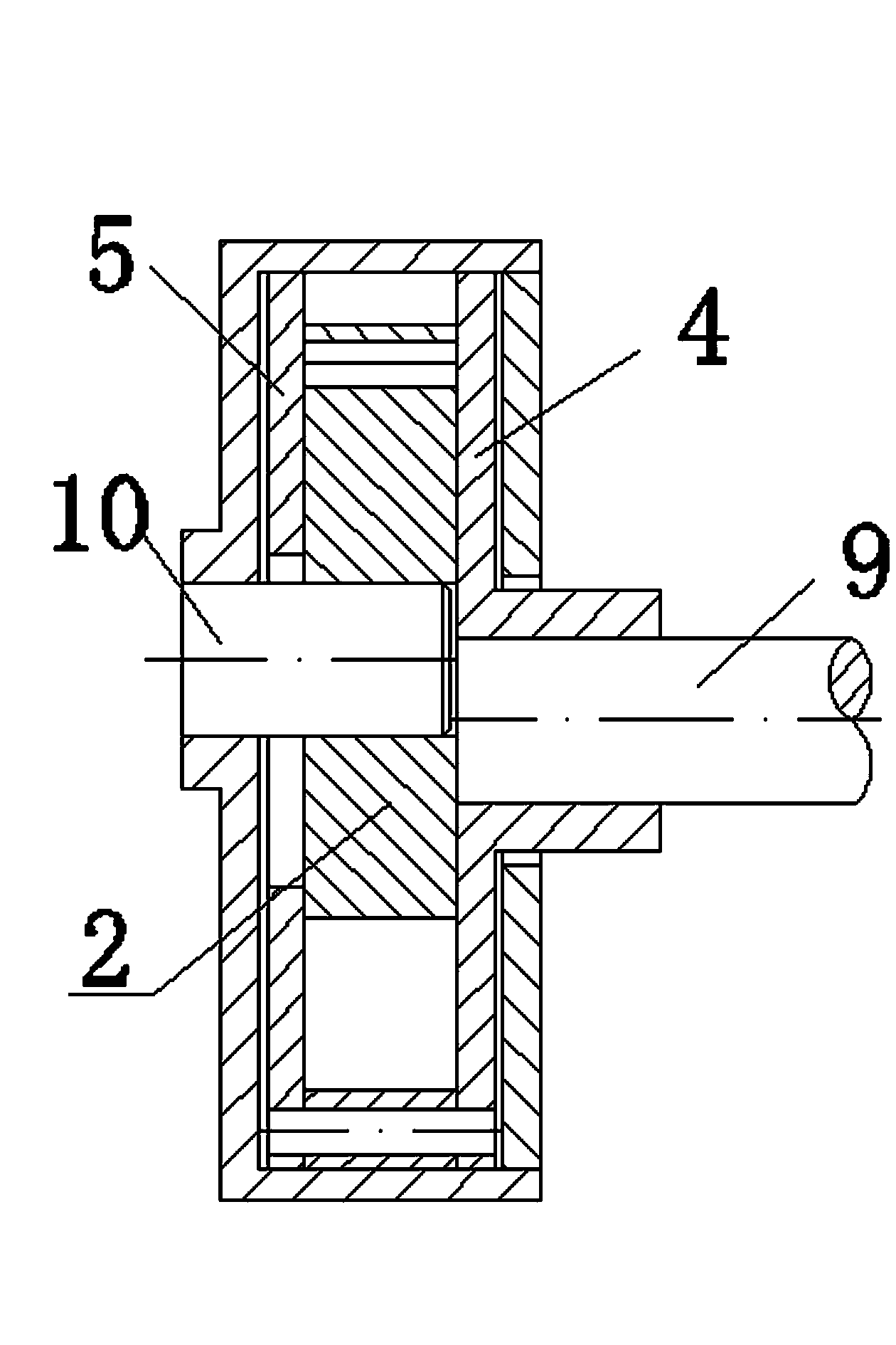
[0017] Such as figure 1 As shown, the present invention provides a composite rotor power machine, the power machine includes a casing 1 and a composite rotor arranged in the casing 1, the inside of the casing 1 is a circular cavity, and the composite rotor is arranged in the circular cavity of the casing 1 In the cavity; the composite rotor includes a front cover 4, a rear cover 5, a rotor wheel 2 and a plurality of flexible rotor arms 3 arranged on the rotor wheel 2; the front cover 4 is arranged in front of the casing 1, and the rear cover 5 It is arranged at the back of the casing 1, the front cover 4 and the rear cover 5 can rotate relative to the casing 1, and the outer circles of the front cover 4 and the rear cover 5 are dynamically sealed with the inner wall of the casing 1; the rotor wheel 2 And the flexible rotor arm 3 is arranged betwee...


PUM


Abstract

The invention relates to a power machine which comprises a machine shell and a combined rotor, wherein the combined rotor is arranged in the machine shell; the machine shell is internally provided with a circular cavity; the combined rotor is arranged in the circular cavity of the machine shell and comprises a front cover plate, a rear cover plate, a rotor wheel and a plurality of flexible rotor arms; the flexible rotor arms are arranged on the rotor wheel; the front cover plate is arranged on the front surface of the machine shell; the rear cover plate is arranged on the rear surface of the machine shell; the front cover plate and the rear cover plate can both rotate relative to the machine shell; the external circles of the front cover plate and the rear cover plate are dynamically sealed with the inner wall of the machine shell. According to the invention, the working operation is realized through the rotation of the front cover plate of the combined rotor. The power machine disclosed by the invention has the advantages of simple structure, easiness for processing and manufacturing, high operating efficiency, energy conservation and wide universality.

Description

technical field [0001] The invention belongs to the technical field of volumetric power machines, and mainly utilizes industrial waste heat and other organic working medium energy medium fluids to cool down, depressurize, flash and expand to do work, and drives a generator to generate electricity; pumps, fans, etc. operate. It can also be used as a booster transfer pump for pumping various fluids. Background technique [0002] At present, the volumetric power machines commonly used at home and abroad mainly include: gas-liquid full-flow screw expansion power machines; reciprocating piston expansion power machines; scroll expansion power machines, etc. The structures of the above-mentioned various volumetric power machines are relatively complex, difficult to process and manufacture, and have low efficiency. Contents of the invention [0003] Purpose of the invention: The present invention provides a composite rotor power machine, which aims to solve the problems of comple...

Claims


Application Information

Patent Timeline
Patent Type & Authority Applications(China)
IPC IPC(8): F01C1/00F01C13/00F01C13/04
Inventor 白明
Owner 白明
Why Eureka
Try Eureka