
Hydro-pneumatic suspension system and wheeled vehicle with same

A technology of oil-pneumatic suspension and left suspension, which is applied to the interconnection system, vehicle components, suspension, etc., can solve the problems of inability to realize the active lifting and lowering of the axle, cannot meet the road traffic conditions, and there are few road driving modes, so as to improve road adaptability capability, improved maintainability, and leak-free results

Active Publication Date: 2011-05-18
SANY HEAVY IND CO LTD (CN)
View PDF6 Cites 46 Cited by
  • Summary
  • Abstract
  • Description
  • Claims
  • Application Information

AI Technical Summary

Problems solved by technology

This existing oil-pneumatic suspension control circuit must passively retract the suspension oil cylinder through the weight of the vehicle, and the active lifting of the axle cannot be realized in the non-load-bearing state
In addition, this oil-pneumatic suspension technology has fewer road driving modes and cannot meet the requirements of various complex road traffic conditions.

Method used


Image

  • Hydro-pneumatic suspension system and wheeled vehicle with same
  • Hydro-pneumatic suspension system and wheeled vehicle with same
  • Hydro-pneumatic suspension system and wheeled vehicle with same

Examples


Embodiment Construction

[0031] The embodiments of the present invention will be described in detail below with reference to the accompanying drawings, but the present invention can be implemented in many different ways defined and covered by the claims.

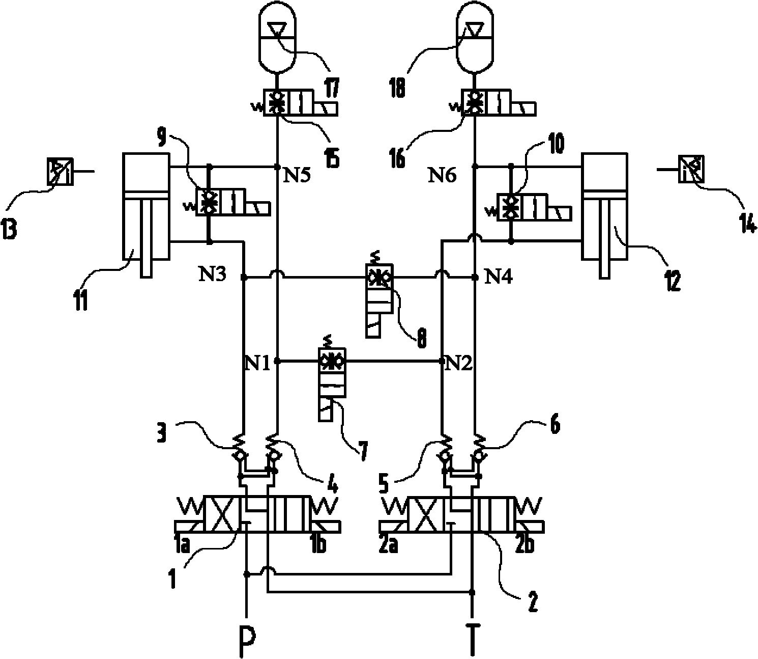
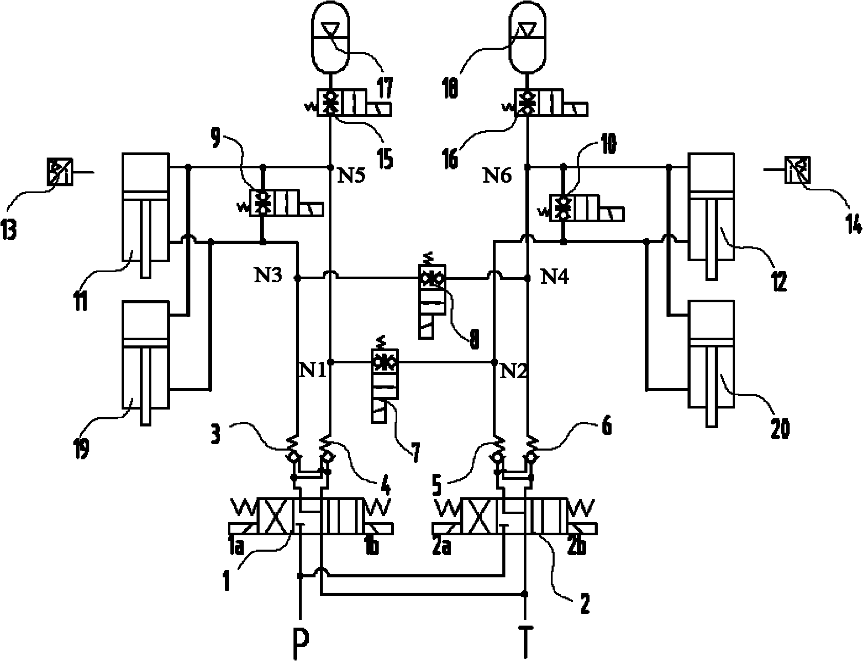
[0032] Such as figure 1As shown, it is a schematic diagram of the implementation of the hydraulic principle of single-axle suspension. The oil-pneumatic suspension device for wheeled vehicles provided in this embodiment includes a left reversing valve 1, a right reversing valve 2, a first hydraulic control check valve 3. The second hydraulic control check valve 4, the third hydraulic control check valve 5, the fourth hydraulic control check valve 6, the first on-off valve 7, the second on-off valve 8, the third on-off valve 9, The fourth on-off valve 10, the fifth on-off valve 15, the sixth on-off valve 16, the left hanging oil cylinder 11, the right hanging oil cylinder 12, the left accumulator 17, the right accumulator 18, and each oil circuit are...


PUM


Abstract

The invention discloses a hydro-pneumatic suspension system and a wheeled vehicle with the same. The hydro-pneumatic suspension system comprises a left suspension oil cylinder, a right suspension oil cylinder, a left change valve, a right change valve, a first hydraulic locking structure and a second hydraulic locking structure. The left suspension oil cylinder and the right suspension oil cylinder are respectively provided with a rod cavity and a rodless cavity. The left change valve and the right change valve are three-position four-way valves and are respectively provided with a first oil opening and a second oil opening, a pressure oil opening connected with a pressure oil source and an oil return opening connected with an oil tank. The first hydraulic locking structure is connected between the left suspension oil cylinder and the left change valve. The second hydraulic locking structure is connected between the right suspension oil cylinder and the right change valve. The left change valve and the right change valve are respectively provided with a first state, a second state and a third state, wherein the first state enables the first working oil opening and the second working oil opening to be connected to the oil return opening; the second state enables the first working oil opening to be connected to the oil return opening and the second working oil opening to be connected to the pressure oil opening; the third state enables the first working oil opening to be connected to the pressure oil opening and the second working oil opening to be connected to the oil return opening. In the invention, the hydro-pneumatic suspension system and the wheeled vehicle can realize the active lifting of vehicle axles under the nonload bearing state.

Description

technical field [0001] The invention relates to an oil-air suspension system of a wheeled vehicle, and to a wheeled vehicle with the oil-air suspension system. The invention is especially suitable for multi-axle wheeled vehicles in which at least one pair of suspension oil cylinders work together. Background technique [0002] Oil-air suspension is a suspension device that integrates elastic elements and shock absorbers. It overcomes the linear characteristics of leaf springs and is applied to engineering vehicles. It has good vibration reduction performance, ride comfort and vehicle driving stability, and can achieve vehicle height Adjustability. Among the existing oil-air suspension technical solutions for wheeled vehicles, there are independent oil-air suspension and connected oil-air suspension, both of which have their own advantages and disadvantages. For example, independent oil-air suspension is generally used on dump trucks, and connected oil-air suspension is gen...

Claims


Application Information

Patent Timeline
IPC IPC(8): B60G17/0165B60G17/08
CPCB60G17/0432B60G21/073
Inventor 邹兴龙周丽云周济新
Owner SANY HEAVY IND CO LTD (CN)
Learn More