Short and straight section row bending device of boiler diaphragm type wall

A membrane wall and top bending technology, which is applied in the manufacture of boiler membrane walls, can solve the problems of high material cost and waste of materials, and achieve the effect of reducing waste and cost

Inactive Publication Date: 2013-03-20
WUXI HUAGUANG BOILER
View PDF0 Cites 0 Cited by
  • Summary
  • Abstract
  • Description
  • Claims
  • Application Information

AI Technical Summary

Problems solved by technology

[0002] For the structure of the short straight section of the boiler membrane wall, see figure 1 , which includes two sections of arc 1, 2, and a short straight section 3 between arc 1 and arc 2, the length of which is L; when the existing boiler membrane wall is manufactured, the membrane wall is generally used in rows of top bends The special plane bends the short straight sections of the membrane wall in rows. The structure of the existing row-top bending special plane is shown figure 2 , which includes a top pressure roller 4 and two end side rollers 5. The workpiece 6 is placed on the end faces of the two end side rollers 5. The top arc surface of the top pressure roller 4 is mounted on the workpiece 6, so that the workpiece 6 is bent. Due to the membrane type The length L of the short straight section 3 of the wall is less than the minimum straight line length of the row of top bending machines, so during the bending process of the workpiece, it is necessary to leave a technological allowance for the workpiece. After the workpiece is bent, the technological allowance is cut off. The size of the top bending machine is fixed, and the process allowance is usually relatively large, which wastes a lot of materials and makes the material cost high

Method used


Image

  • Short and straight section row bending device of boiler diaphragm type wall
  • Short and straight section row bending device of boiler diaphragm type wall
  • Short and straight section row bending device of boiler diaphragm type wall

Examples


Embodiment Construction

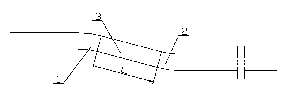
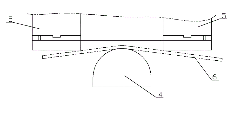
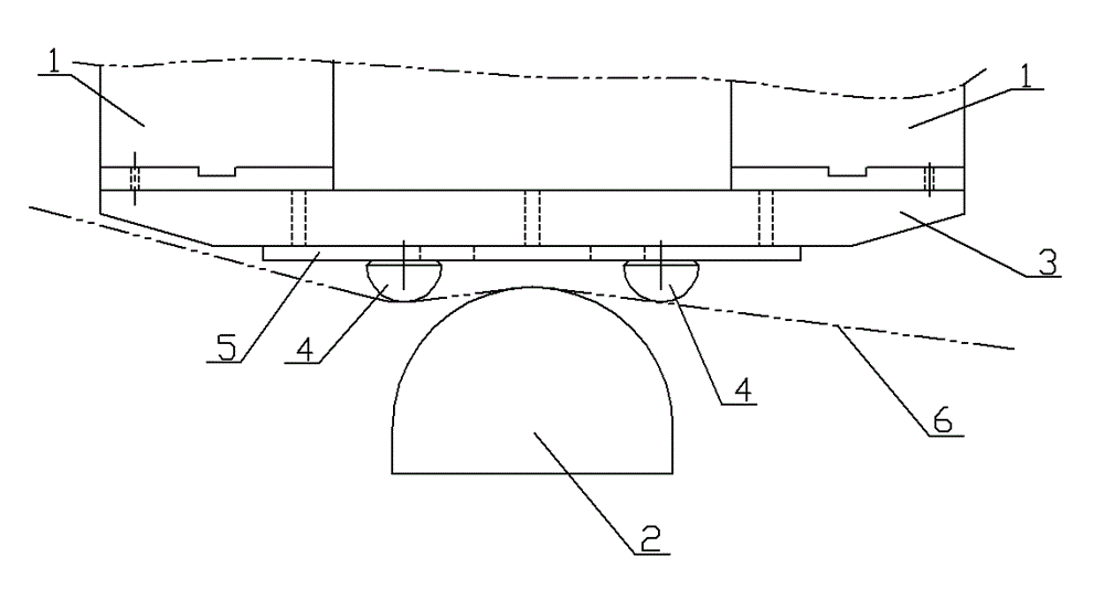
[0010] See image 3 , which includes side rollers 1 at both ends and a pressure roller 2 in the middle position, the top surface of the pressure roller 2 is an arc surface, and the end surfaces of the side rollers 1 at both ends close to the pressure roller 2 are tightly connected to the top bending support member 3, Both sides of the top bending support member 3 are respectively fastened to connect the side rollers 1 at both ends, and the both sides of the middle position near the end face of the top pressure roller of the top bending support member 3 are equipped with a forming semi-cylindrical wheel 4, and the circle of the forming semi-cylindrical wheel 4 The arc surface faces the top pressure roller 2, and a reinforcing rib 5 is fastened between the formed semi-cylindrical wheel 4 and the top bending support member 3. Figure 6 is the schematic structure of the workpiece.


PUM


Abstract

The invention provides a short and straight section row bending device of a boiler diaphragm type wall which can reduce the waste of materials, and reduce the material cost. The technical scheme of the short and straight section row bending device of the boiler diaphragm type wall is as follows: the short and straight section row bending device of the boiler diaphragm type wall comprises side rollers at two ends, an ejecting roller, and the top surface of the ejecting roller is an arc surface. The short and straight row bending device of the boiler diaphragm type wall is characterized in that the side rollers at two ends which are close to the end surface of the ejecting roller are connected with a top bending supporting member in a fastening mode; the two sides of the top bending supporting member are respectively connected with the side rollers at two ends in a fastening mode; the both sides of the middle position, close to the end surface of the ejecting roller, of the top bending supporting member are provided with molding semicircular column wheels; and the arc surfaces of the molding semicircular column wheels face the ejecting roller.

Description

technical field [0001] The invention relates to the field of manufacturing boiler membrane walls, in particular to a top bending device for rows of short straight sections of the boiler membrane walls. Background technique [0002] For the structure of the short straight section of the boiler membrane wall, see figure 1 , which includes two sections of arc 1, 2, and a short straight section 3 between arc 1 and arc 2, the length of which is L; when the existing boiler membrane wall is manufactured, the membrane wall is generally used in rows of top bends The special plane bends the short straight sections of the membrane wall in rows. The structure of the existing row-top bending special plane is shown figure 2 , which includes a top pressure roller 4 and two end side rollers 5. The workpiece 6 is placed on the end faces of the two end side rollers 5. The top arc surface of the top pressure roller 4 is mounted on the workpiece 6, so that the workpiece 6 is bent. Due...

Claims


Application Information

Patent Timeline
Patent Type & Authority Patents(China)
IPC IPC(8): B21D5/08
Inventor 蒋荣民
Owner WUXI HUAGUANG BOILER
Why Eureka
Try Eureka