Extended Field of View Ultrasound Imaging with 2D Array Probes

A two-dimensional array and array technology, applied in the field of medical diagnostic ultrasound systems, can solve problems such as expensive systems

Active Publication Date: 2015-08-19
KONINKLIJKE PHILIPS ELECTRONICS NV
View PDF17 Cites 0 Cited by
  • Summary
  • Abstract
  • Description
  • Claims
  • Application Information

AI Technical Summary

Problems solved by technology

However, this method is limited in that it can only estimate probe motion in preset directions set by the orientation of the tracking array
Furthermore, such systems are relatively expensive since multiple arrays must be fabricated in a single probe and operated simultaneously

Method used


Image

  • Extended Field of View Ultrasound Imaging with 2D Array Probes
  • Extended Field of View Ultrasound Imaging with 2D Array Probes
  • Extended Field of View Ultrasound Imaging with 2D Array Probes

Examples


Embodiment Construction

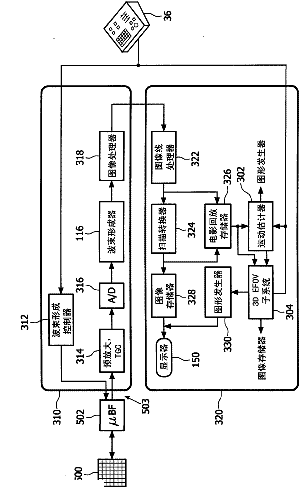
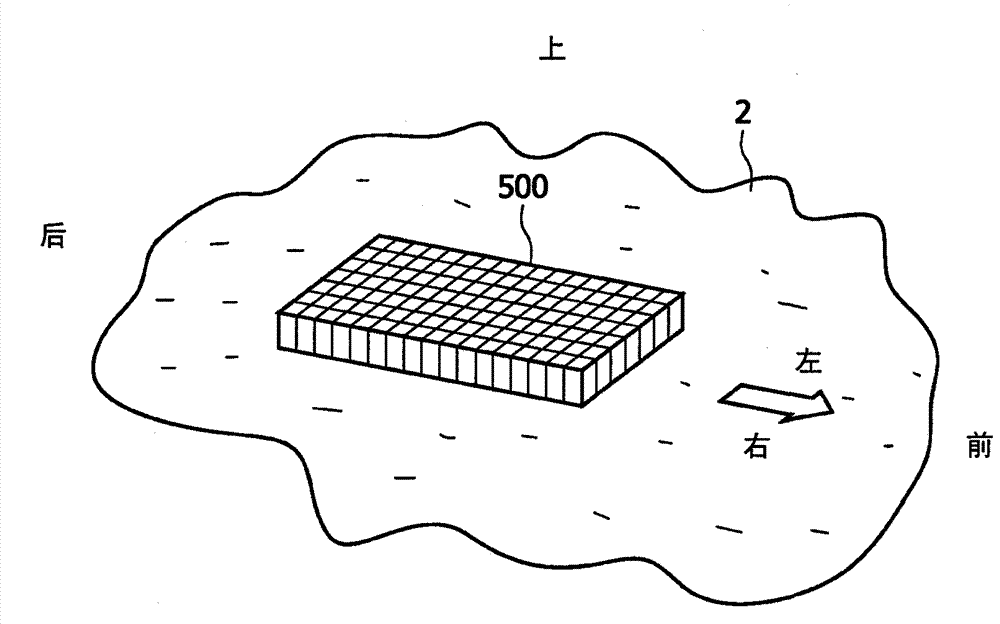
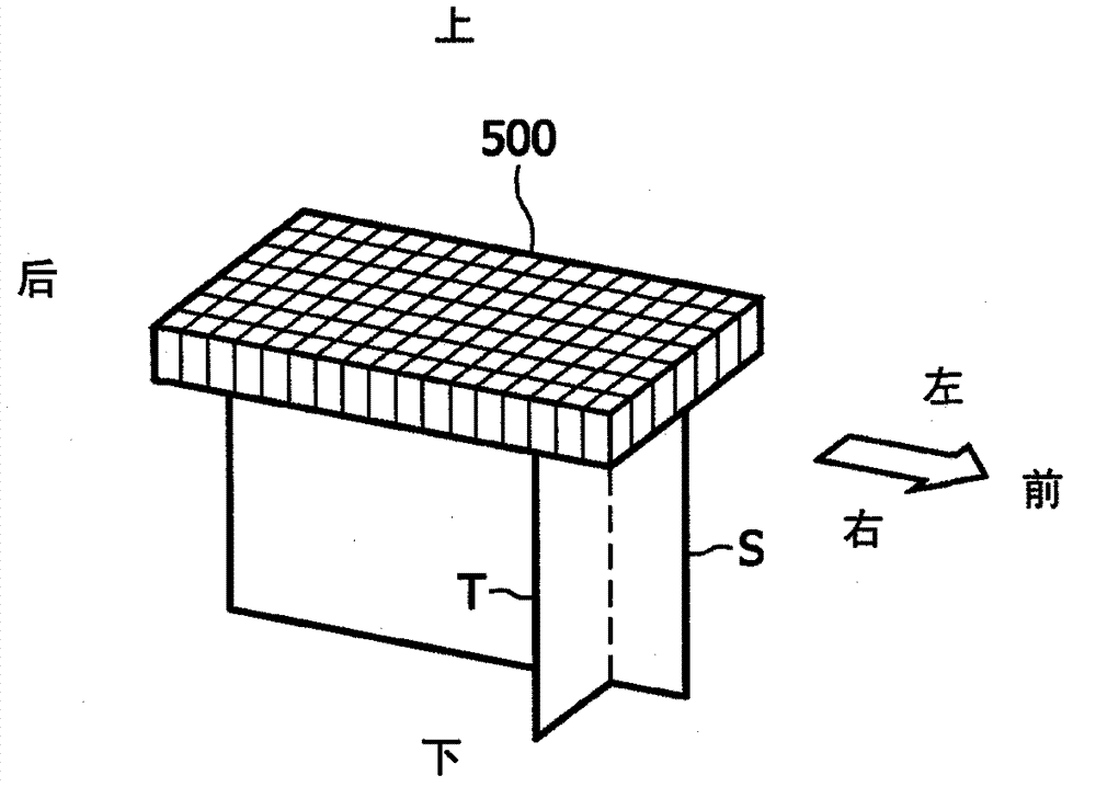
[0024] first reference figure 1 , shows in block diagram form an ultrasound system constructed in accordance with the principles of the present invention. The probe is coupled to the system comprising a two-dimensional array transducer 500 and a microbeamformer 502 . The microbeamformer includes circuitry that controls the signals applied to groups of elements ("patches") of the array transducer 500 and performs some processing on the echo signals received by each group of elements. A microbeamformer in the probe advantageously reduces the number of conductors in the cable 503 between the probe and the ultrasound system, and is described in US Patent 5,997,479 (Savord et al.) and US Patent 6,436,048 (Resque).

[0025]The probe is coupled to the scanner 310 of the ultrasound system. The scanner includes a beamforming controller 312 that is responsive to the user controls 36 and provides control signals to the microbeamformer 502 to instruct the probe as to the timing, frequen...


PUM


Abstract

An ultrasonic diagnostic imaging system produces an extended field of view (EFOV) image. A 3D imaging probe is moved along the skin of a patient above the anatomy which is to be included in the EFOV image. As the probe is moved, images are acquired from a plurality of differently oriented image planes such as a sagittal plane and a transverse plane. As the probe is moved the image data of successive planes of one of the orientations is compared to estimate the motion of the probe. These motion estimates are used to position a succession of images acquired in one of the orientations accurately with respect to each other in an EFOV display format. The display format may be either a 2D EFOV image or a 3D EFOV image.

Description

technical field [0001] The present invention relates to medical diagnostic ultrasound systems, and, more particularly, to ultrasound systems that perform panoramic or extended field of view (EFOV) imaging. Background technique [0002] Two-dimensional extended field of view (EFOV) or panoramic ultrasound imaging is a useful tool for visualizing larger or longer structures (eg, femoral artery, carotid artery) that cannot be fully viewed in conventional ultrasound imaging. In two-dimensional (2D) panoramic imaging, as described in U.S. Patent 6,442,289 (Olsson et al.), a large number of 2D image. The acquired overlapping images are combined to generate a panoramic image by utilizing probe motion estimation, typically measured by evaluating registration between consecutive overlapping images. As shown in US Patent 6,516,215 (Roundhill), very long images can be viewed better on wide aspect ratio displays. A limitation of conventional extended field imaging using one-dimension...

Claims


Application Information

Patent Timeline
IPC IPC(8): G01S7/52G01S15/89
CPCG01S7/52065G01S15/8993G01S7/52074G01S7/52073A61B8/4245A61B8/483G01S7/5205
Inventor Y·余J·杰戈J-M·钟R·恩特金M·安德森L·J·奥尔森
Owner KONINKLIJKE PHILIPS ELECTRONICS NV
Why Eureka
Try Eureka