
Air knocker with minimized impact

A vibrator and pneumatic technology, applied in the direction of portable impact tools, striking tools, pollution prevention methods, etc., can solve the problems of reducing magnetic piston recovery and so on

Inactive Publication Date: 2011-05-04
金景大
View PDF0 Cites 0 Cited by
  • Summary
  • Abstract
  • Description
  • Claims
  • Application Information

AI Technical Summary

Problems solved by technology

[0010] The present invention is proposed to solve the problems of the conventional air vibrator, and its purpose is to prevent vibration and noise by reducing the impact when the magnetic piston returns.

Method used


Image

  • Air knocker with minimized impact
  • Air knocker with minimized impact
  • Air knocker with minimized impact

Examples


Embodiment Construction

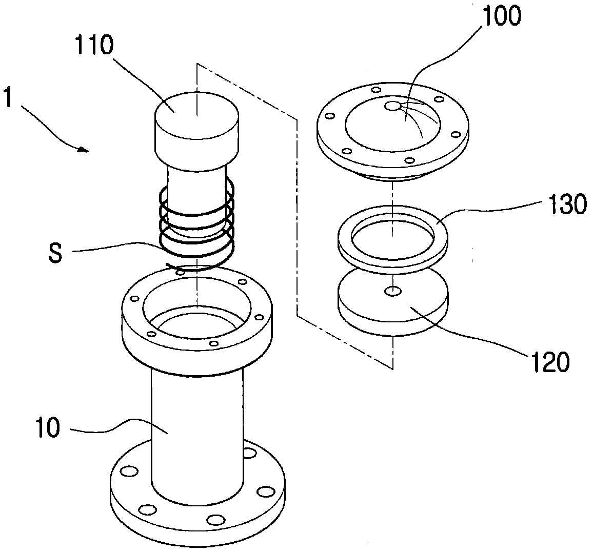
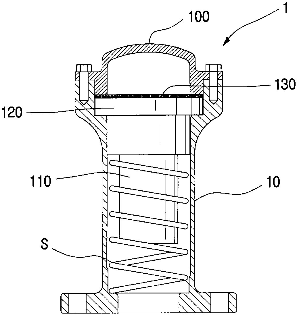
[0020] The pneumatic vibrator 1 of the present invention has a magnetic piston 110 under the elastic force of a spring S inside the cylinder 10, and a cylinder head 100 is connected to the upper part of the cylinder 10 by bolts, and the inside of the cylinder head 100 is equipped with a magnetic piston 110 for fixing. The fixed plate 120 of the magnetic piston 110 forms an insertion groove 111 at the end of the magnetic piston 110, and the insertion groove 111 is provided with a cushioning material 112 for absorbing the shock generated when the magnetic piston 110 strikes the powder tank 2. impact or noise.

[0021] The specific implementation of the present invention will be described in detail through the embodiments shown in the drawings.

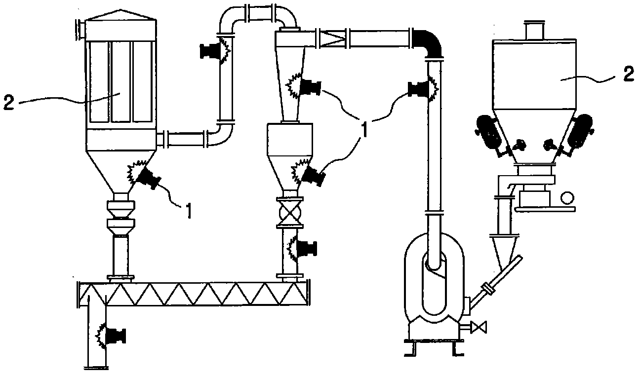
[0022] figure 1 is a schematic diagram showing a state of use of an embodiment of the present invention, figure 2 is an exploded perspective view showing the composition of an embodiment of the present invention, image 3 is a combin...


PUM


Abstract

The present device relates to an air knocker that strikes wall surfaces of a powder storage tank such as a silo, hopper, etc. to prevent the function of the powder storage tank from being degraded. An aim of the present device is to solve the conventional problems by minimizing the impact generated when a magnetic piston returns to a cylinder head of the air knocker after striking. Another aim of the present device is to maintain the striking pressure of the magnetic piston by preventing a clearance at a fixing plate in the cylinder head and thus preventing air loss, and a further aim of the present device is to prevent vibration and noise by minimizing the impact during the return of the magnetic piston. To accomplish the above aims of the present device, a buffering ring is provided in the cylinder head to buffer the pressure generated during the return of the magnetic piston, thus preventing pressure from being generated in the cylinder head by the return of the magnetic piston.

Description

technical field [0001] The present invention relates to a pneumatic vibrator, which is used to prevent the wall surface of a powder tank such as a silo (Silo) or a funnel (Hopper) from being reduced and the function of the powder tank to be reduced. More specifically, it relates to a pneumatic vibrator that reduces impact. It is possible to prevent the function of the air shaker from being reduced or the assembly part damaged due to the vibration generated when the air shaker hits the wall surface of the powder tank. Background technique [0002] Generally, the inner wall surface of powder tanks such as silos, hoppers, and cyclones for storing or transporting powdery objects such as feed is degraded due to adhesion of powdery objects or the phenomenon of ratholes. To prevent this phenomenon, use high-pressure Vibration is applied by hammering the wall of the powder tank to prevent powder adhesion or rathole phenomenon. [0003] In the conventional pneumatic vibrator 1, its ...

Claims


Application Information

Patent Timeline
IPC IPC(8): B65G11/02
CPCB08B7/02B08B9/08B08B17/00B25D9/26B65G11/026B65G11/206B65G43/00B65G47/18B65G2201/042B65G2207/40
Inventor 金景大
Owner 金景大
Learn More