Positioning installing structure for stator core of motor and base

A motor stator and stator core technology, which is applied in the direction of electromechanical devices, electrical components, electric components, etc., can solve the problems of inability to absorb vibration, weak welding, and potential safety hazards, so as to reduce rework, facilitate connection, and ensure normal operation. Effect

Active Publication Date: 2013-01-30
上海电气集团上海电机厂有限公司
View PDF0 Cites 0 Cited by
  • Summary
  • Abstract
  • Description
  • Claims
  • Application Information

AI Technical Summary

Problems solved by technology

[0003] In the above-mentioned positioning structure of the motor stator core and the machine base, since there are manufacturing errors in the stator core, the elastic feet and the inner bottom surface of the machine base, after the support ribs are inserted into the rectangular holes on the end plates at both ends of the stator core, if the rectangular The holes and the supporting ribs are matched without gaps, so there is no room for floating between them. Therefore, the elastic feet and the inner bottom surface of the machine base or a surface of the supporting ribs cannot be completely fitted, and there is an inclination or a gap, which cannot play a role. The role of shock absorption
If the rectangular hole on the end plate fits with the supporting rib with a large gap, the gap after the supporting rib is inserted into the rectangular hole is too large, and the welding will appear virtual welding, so there is a big safety hazard

Method used


Image

  • Positioning installing structure for stator core of motor and base
  • Positioning installing structure for stator core of motor and base
  • Positioning installing structure for stator core of motor and base

Examples


Embodiment Construction

[0017] In order to better understand the technical solution of the present invention, it will be described in detail below through specific embodiments in conjunction with the accompanying drawings:

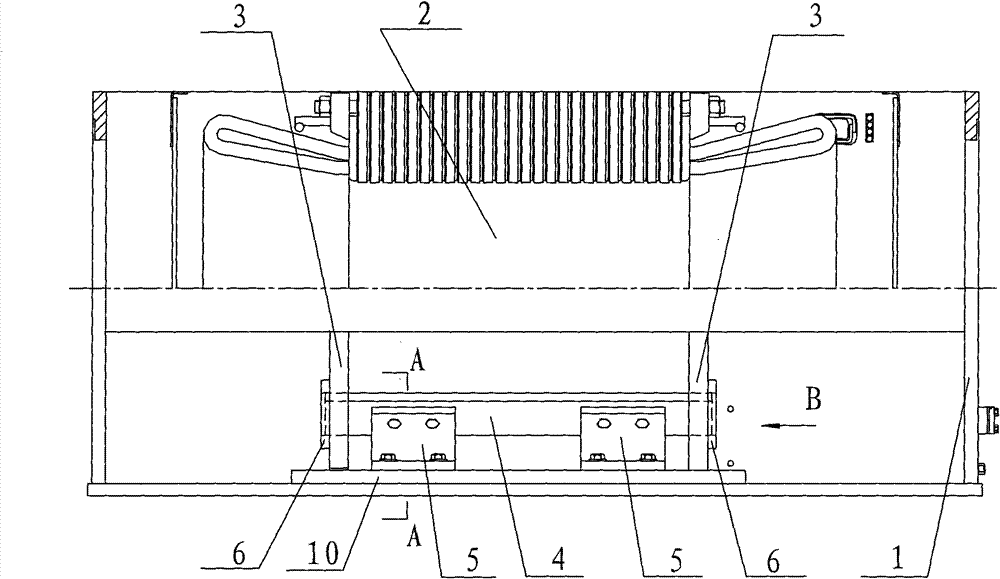
[0018] see figure 2 with image 3 , a positioning installation structure of a motor stator core and a machine base according to the present invention, comprising a machine base 1, a stator core 2, two end pressure plates 3, a support rib 4, two elastic feet 5 and two positioning sleeve plates 6 ,in,

[0019] The end plate 3 is located at both ends of the stator core 2; the cross section of the support rib 4 is rectangular;

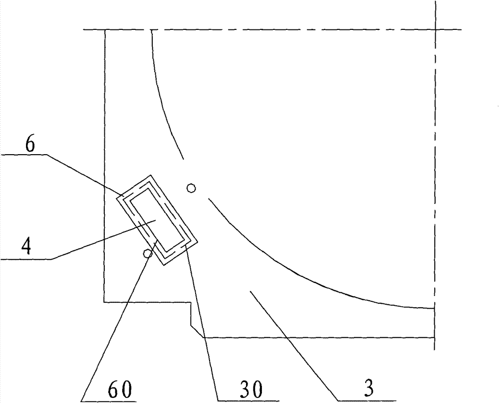
[0020] The lower side of the end plate 3 is provided with a rectangular hole 30 with an angle of 55° with the inner bottom surface 10 of the machine base 1. The length and width of the rectangular hole 30 are respectively 18 to 18% larger than the length and width of the section of the support rib 4. 22mm;

[0021] The supporting ribs 4 are bridged on th...


PUM


Abstract

The invention discloses a positioning installing structure for a stator core of a motor and a base, which can eliminate the oscillation phenomenon of the motor and comprises a supporting rib, an elastic foot margin and two positioning sleeve plates, wherein the elastic foot margin is bent into a bent steel plate having an included angle of 55 degrees and the bent side thereof is fixedly connected with one side wall of the supporting rib; a rectangular hole on an end clamp plate is bigger than the cross section of the supporting rib; two ends of the supporting rib are respectively moveably inserted into the rectangular hole on the end clamp plate at two ends of the stator core and then are extended out of the outer side wall of the end clamp plate; the areas of the positioning sleeve plates are bigger than the area of the rectangular hole on the end clamp plate; a rectangular inner hole matched with the supporting rib is arranged on the center of the positioning sleeve plates; the two positioning sleeve plates are respectively sleeved on two ends of the supporting rib positioned on the outer side wall of the end clamp plate; and after the bottom plane of the elastic foot margin is fitted and fixedly connected with the inside bottom plane of the engine base, the inner surface of the rectangular inner hole on the positioning sleeve plates is welded with the outer surface of the supporting rib and the outer edge of the sleeve plates is welded with the end clamp plate.

Description

technical field [0001] The invention relates to a positioning structure of a motor component, in particular to a positioning installation structure of a motor stator iron core and a machine base. Background technique [0002] At present, the stator core of the box-type high-speed motor is generally installed in cooperation with the inner bottom surface of the frame through the support ribs and elastic feet to achieve the effect of vibration absorption, so a good fit and installation is very important. Both ends of the stator core are provided with end plates, and the lower part of the end plate is provided with a rectangular hole matching the cross-sectional shape of the support rib. The two ends of the support rib are inserted into the rectangular holes on the end plate and then fixedly connected to the end plate by welding; The elastic feet are bent steel plates bent into an included angle of 55°. The bottom plane of the elastic foot is fixed on the inner bottom surface o...

Claims


Application Information

Patent Timeline
Patent Type & Authority Patents(China)
IPC IPC(8): H02K5/24
Inventor 王建平
Owner 上海电气集团上海电机厂有限公司
Why Eureka
Try Eureka