
Method for measuring focus point of exposure machine

A focus point and exposure machine technology, which is applied to microlithography exposure equipment, photolithography process exposure devices, etc., can solve the problems of too large focus point drift and too long measurement time of the exposure machine that cannot be found, and achieves short measurement time. The effect of high calculation accuracy and high efficiency

Active Publication Date: 2012-05-30
CSMC TECH FAB2 CO LTD
View PDF0 Cites 0 Cited by
  • Summary
  • Abstract
  • Description
  • Claims
  • Application Information

AI Technical Summary

Problems solved by technology

[0007] The problem to be solved by the present invention is to provide a method for measuring the focus point of the exposure machine to prevent the measurement time from being too long, and it is impossible to find that the focus point of the exposure machine drifts too much

Method used


Image

  • Method for measuring focus point of exposure machine
  • Method for measuring focus point of exposure machine
  • Method for measuring focus point of exposure machine

Examples


Embodiment Construction

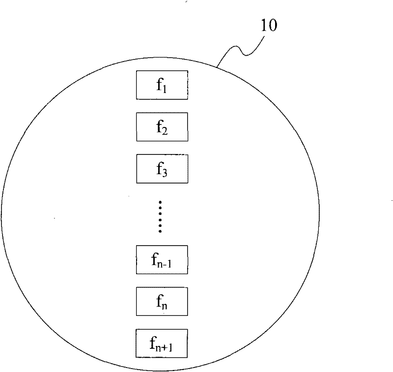
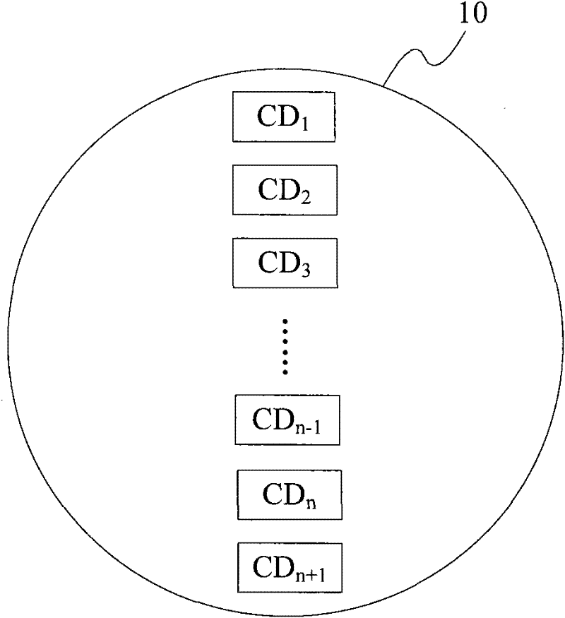
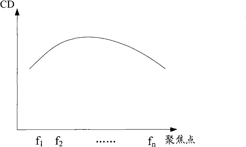
[0017] In the existing method of measuring the best focus point of the exposure machine, due to the large number of measurement points, the measurement time is too long and the measurement efficiency is reduced; in addition, the excessive drift of the focus point of the exposure machine cannot be found in time. The present invention establishes a database according to the relationship between measuring the overlay value of the overlay mark and the focal length; and can directly calculate the value of the focus point of the exposure machine in the manufacturing process of the semiconductor device according to the data therein and the overlay value between the patterns on the photoresist layer , the measurement time is short, and the efficiency is high; and the situation that the focus point of the exposure machine drifts too much can be found in time. In addition, a database is established by measuring the relationship between the overlay value of the overlay mark and the focal ...


PUM


Abstract

The invention relates to a method for measuring a focus point of an exposure machine, which comprises the following steps of: providing a photomask plate with an overlay mark which is provided with at least two parallel lines; forming a displacement line on the outer edge of either of the two parallel lines, so that a test line is formed by the displacement line and the line, wherein the length of the displacement line is equal to that of the outer edge; transferring the overlay mark on the photomask plate onto an optical resist layer to form an overlay mark graph which contains a test line graph; measuring overlay values; establishing a database according to the relation between the overlay values and corresponding exposure focus points, which is obtained by transferring the displacementline to different positions; measuring an overlay value between two parallel graphs after transferring a random graph on the photomask plate onto a wafer through the exposure machine; and obtaining the focal length of the focus point of the exposure machine according to the overlay value between the graphs, which is obtained by calculation, and a data value in the database. The method has short measurement time and high efficiency.

Description

technical field [0001] The invention relates to a method for testing a semiconductor device, in particular to a method for measuring the focal point of an exposure machine. Background technique [0002] As the size of devices in the integrated circuit manufacturing process becomes smaller and smaller, the requirements for the photolithography process are also higher and higher. At present, the purpose of exposing smaller-sized patterns is generally achieved by reducing the exposure wavelength of the exposure light source. However, this method of only narrowing the exposure wavelength usually has the problem of insufficient lithographic resolution. Therefore, in order to make the photolithography process meet the requirements of the development of semiconductor devices, it is also necessary to adjust the parameters of the exposure machine. [0003] Exposure machine (Scanner), as an important production machine in the semiconductor process (Semi-conductor Process), is mainly...

Claims


Application Information

Patent Timeline
Patent Type & Authority Patents(China)
IPC IPC(8): G03F7/20
Inventor 杨要华刘志成张辰明胡骏
Owner CSMC TECH FAB2 CO LTD
Learn More