Blood pressure measuring device

A technology for measuring device and blood pressure, which is applied in the direction of cardiac catheterization, etc., and can solve the problems of different detection accuracy of volume change of blood vessels, low detection accuracy of volume change of blood vessels, etc.

Active Publication Date: 2011-04-27
OMRON HEALTHCARE CO LTD
View PDF9 Cites 5 Cited by
  • Summary
  • Abstract
  • Description
  • Claims
  • Application Information

AI Technical Summary

Problems solved by technology

[0007] (2) The larger the volume of the fluid bag, the smaller the density change of the fluid in the fluid bag will be as the volume of the blood vessel changes, so the detection accuracy of the volume change of the blood vessel is lower,
[0009] (4) Even if the pressure of the fluid bag is the same, the volume of the blood vessel will change due to the discharge of the fluid in the fluid bag, and then the volume of the fluid bag will change. Therefore, the detection accuracy of the volume change of the blood vessel is different.
[0010] (5) The more the fluid discharge in the fluid bag is, the smaller the volume change of the fluid bag caused by the volume change of the blood vessel is, so the detection accuracy of the volume change of the blood vessel is lower
[0016] (2) The larger the volume of the fluid bag, the smaller the density change of the fluid in the fluid bag will be as the volume of the fluid bag changes, so the detection accuracy of the volume change of the blood vessel is lower,
[0018] (4) Even if the pressure of the fluid bag is the same, the volume of the blood vessel will change due to the discharge of the fluid in the fluid bag, and then the volume of the fluid bag will change. Therefore, the detection accuracy of the volume change of the blood vessel is different.
[0019] (5) The greater the inflow of fluid into the fluid bag, the smaller the volume change of the fluid bag caused by the volume change of the blood vessel, and therefore the lower the detection accuracy of the volume change of the blood vessel
In addition, as the pressure of the fluid bag changes, the amount of change in the volume change of the blood vessel varies depending on the circumference of the measurement site, so these will cause errors in blood pressure measurement.

Method used


Image

  • Blood pressure measuring device
  • Blood pressure measuring device
  • Blood pressure measuring device

Examples


no. 1 approach

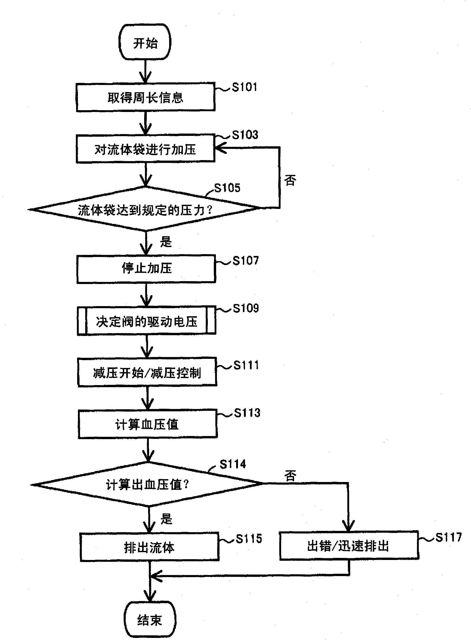
[0133] As a first embodiment, a blood pressure measurement device that measures blood pressure during depressurization of a fluid bag will be described.

[0134] refer to figure 1 A sphygmomanometer 1 as a blood pressure measurement device according to the first embodiment has a main body 2 and a cuff 5 for wrapping (wrapping) a measurement site, and these are connected by a hose 10 . The front of the main body 2 is provided with an operation unit 3 such as a switch and a display unit 4 for displaying measurement results and the like. The operation part 3 includes: a power switch 31 for instructing power on / off (ON / OFF), a measurement switch 32 for instructing the start of the measurement, a stop switch 33 for instructing the stop of the measurement, and a callout ( Store) measured value and display the recording call switch 34. A fluid bag 13 is disposed on the cuff 5 . The fluid injected into the fluid bag 13 and discharged from the fluid bag 13 is, for example, air. By...

Deformed example 1

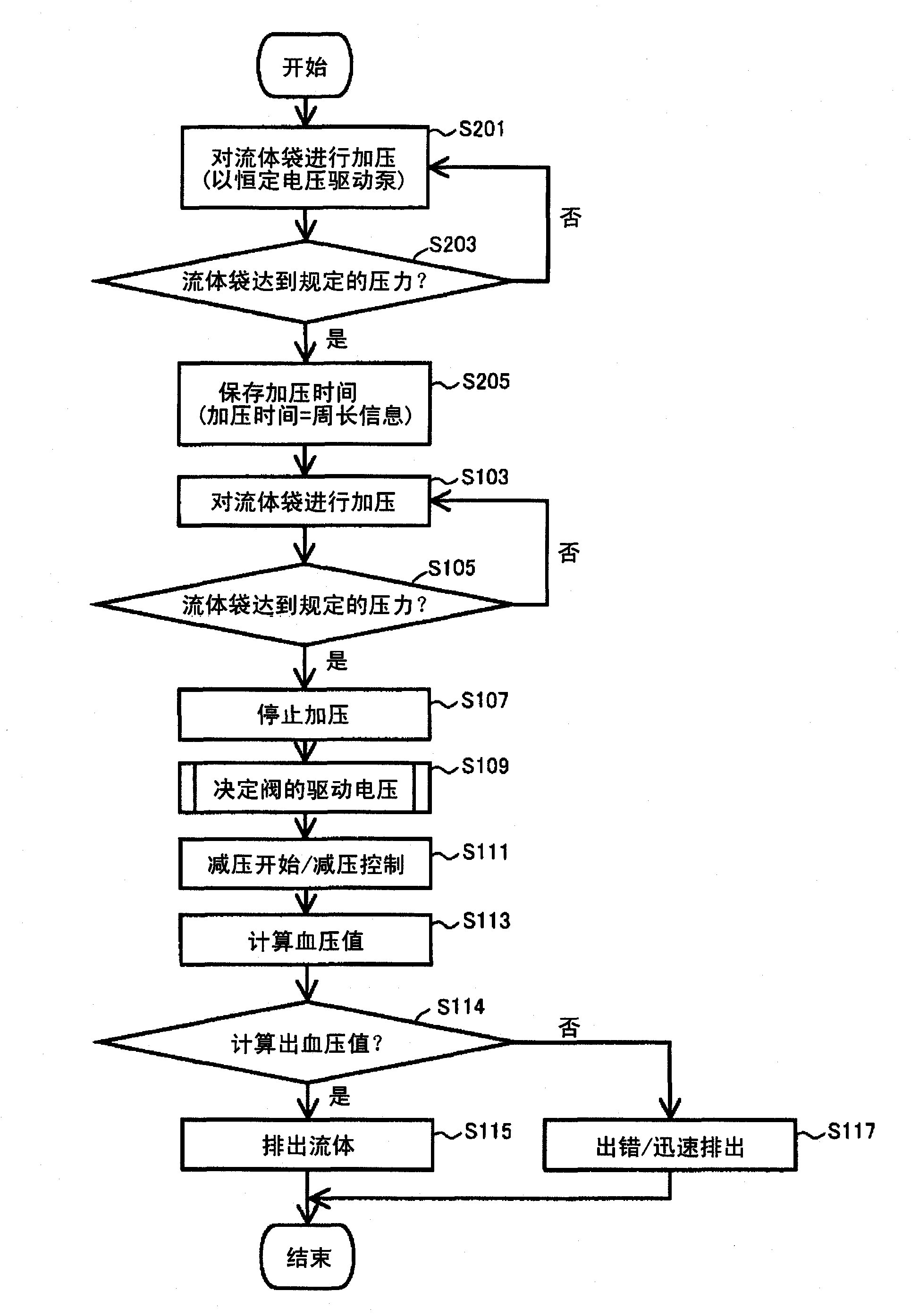
[0151] use Figure 8 A modified example of processing executed when the measurement switch 32 is operated in the sphygmomanometer 1 will be described with reference to the flow chart of FIG. exist Figure 8 shown in the processing, with image 3 In the second specific example shown, similarly, in steps S201 to S205, the circumference of the measurement site is estimated based on the pressurization time until the pressure of the fluid bag 13 reaches a predetermined pressure, and in the subsequent pressurization process, in step S301 The CPU 40 estimates the maximum pressure value based on the change in the internal pressure of the fluid bag 13 obtained from the pressure sensor 23 , and calculates the pressure at the end of pressurization of the fluid bag 13 in step S303 . The sphygmomanometer 1 is configured to calculate a blood pressure value based on a change in internal pressure of the fluid bag 13 obtained during a depressurization process after the fluid bag 13 is pressu...

Deformed example 2

[0162] use Figure 13 The hardware configuration of a sphygmomanometer 1-1 as a modified example of the sphygmomanometer 1 will be described. refer to Figure 13 , sphygmomanometer 1-1 in figure 1 On the basis of the hardware structure of the sphygmomanometer 1 shown, there is also a container 54 connected to the fluid bag 13 by the hose 10, and the container 54 is used to store non-compressible fluid. The container 54 is connected to the pump 51 and the valve 52 . The pump 51 and the valve 52 are respectively connected to a pump driving circuit 56 and a valve driving circuit 57 , and further, the pump driving circuit 56 and the valve driving circuit 57 are respectively connected to the CPU 40 . Based on the operation signal input from the operation unit 3, the CPU 40 executes a predetermined program stored in the memory 6 to determine a voltage for driving the pump 51 and the valve 52, and outputs the determined voltage to the pump drive circuit 56 and the valve drive cir...


PUM


Abstract

Provided is a blood pressure measuring device. In a blood pressure meter, a value representing the circumferential length of a measurement target portion is obtained (S101), a parameter for controlling a voltage for driving a pump is determined based on the obtained value (S401), the voltage for driving the pump is determined based on the parameter and on the pressure in a fluid bag, and the fluid bag is pressurized (S403). In the pressurizing process, a minimum blood pressure value is calculated (S405). Then, a maximum blood pressure value is estimated (S301'), and the pressurization is stopped when the pressure in the fluid bag reaches the maximum blood pressure value (S107). Next, a valve gap for discharging fluid from the fluid bag is determined based on the circumferential length of the measurement target portion (S109), and control for reducing the pressure in the fluid bag with the gap maintained constant is performed (S111). In a pressure reducing process, a maximum blood pressure value is calculated (S112). At the time point when the maximum blood pressure value is calculated, the fluid is discharged from the fluid bag (S115) to complete the measurement.

Description

technical field [0001] The present invention relates to a blood pressure measurement device, and more particularly to a blood pressure measurement device for measuring blood pressure using a cuff (cuff) with a built-in fluid bag. Background technique [0002] As one of the methods of calculating blood pressure with an electronic sphygmomanometer, there is an oscillatory wave induction method, that is, a cuff with a built-in fluid bag is used to wrap a part of the living body, and then the cuff is used to increase and decrease pressure, thereby obtaining the cuff caused by the cuff. The change in the volume of the fluid bag due to the change in the volume of the compressed blood vessel is used as the pressure change (pulse wave amplitude) of the fluid bag to calculate the blood pressure. [0003] The fluid bag has the characteristic that the pressure of the fluid bag is proportional to the volume of the fluid bag Figure 33 relationship shown. That is, refer to Figure 33 , ...

Claims


Application Information

Patent Timeline
Patent Type & Authority Applications(China)
IPC IPC(8): A61B5/0225
CPCA61B5/0225A61B5/02225
Inventor 江藤美佳泽野井幸哉山下新吾
Owner OMRON HEALTHCARE CO LTD
Why Eureka
Try Eureka