
Slew rate control device and method

A control device and slew rate technology, applied in static memory, read-only memory, instruments, etc., can solve the problems of increasing area, affecting the stability of transistors, and many components, and achieving the effect of low power consumption

Active Publication Date: 2011-04-27
SHANGHAI HUAHONG GRACE SEMICON MFG CORP
View PDF5 Cites 9 Cited by
  • Summary
  • Abstract
  • Description
  • Claims
  • Application Information

AI Technical Summary

Problems solved by technology

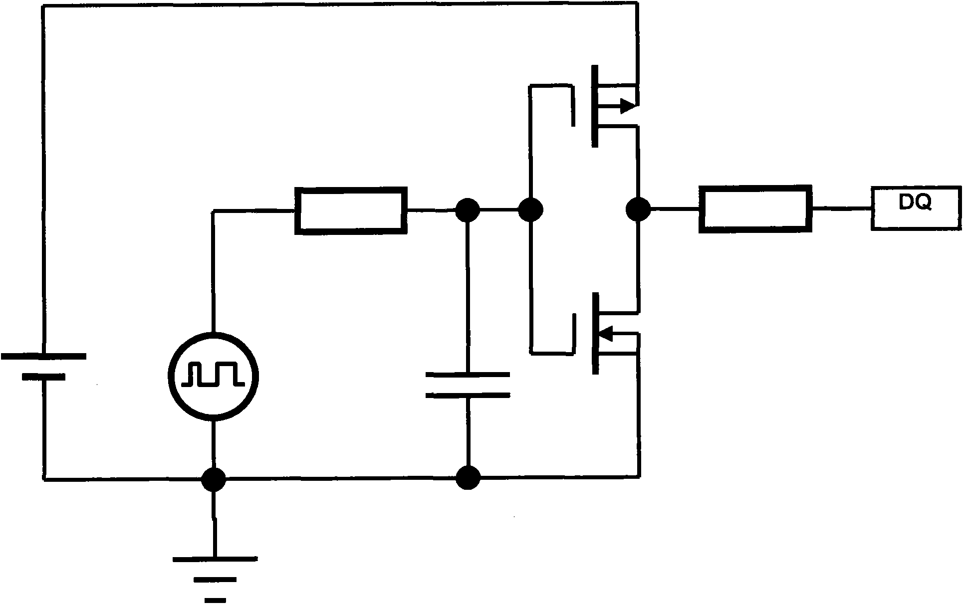
[0004] figure 1 Shown is a single-domain slew rate control circuit in the traditional technology. Since the inconsistency of the manufacturing process will affect the stability of the transistor, and the fluctuation of the input voltage will also affect the slew rate, the disadvantage of this circuit is that the voltage Slew rate varies greatly with manufacturing process, input voltage and temperature fluctuations
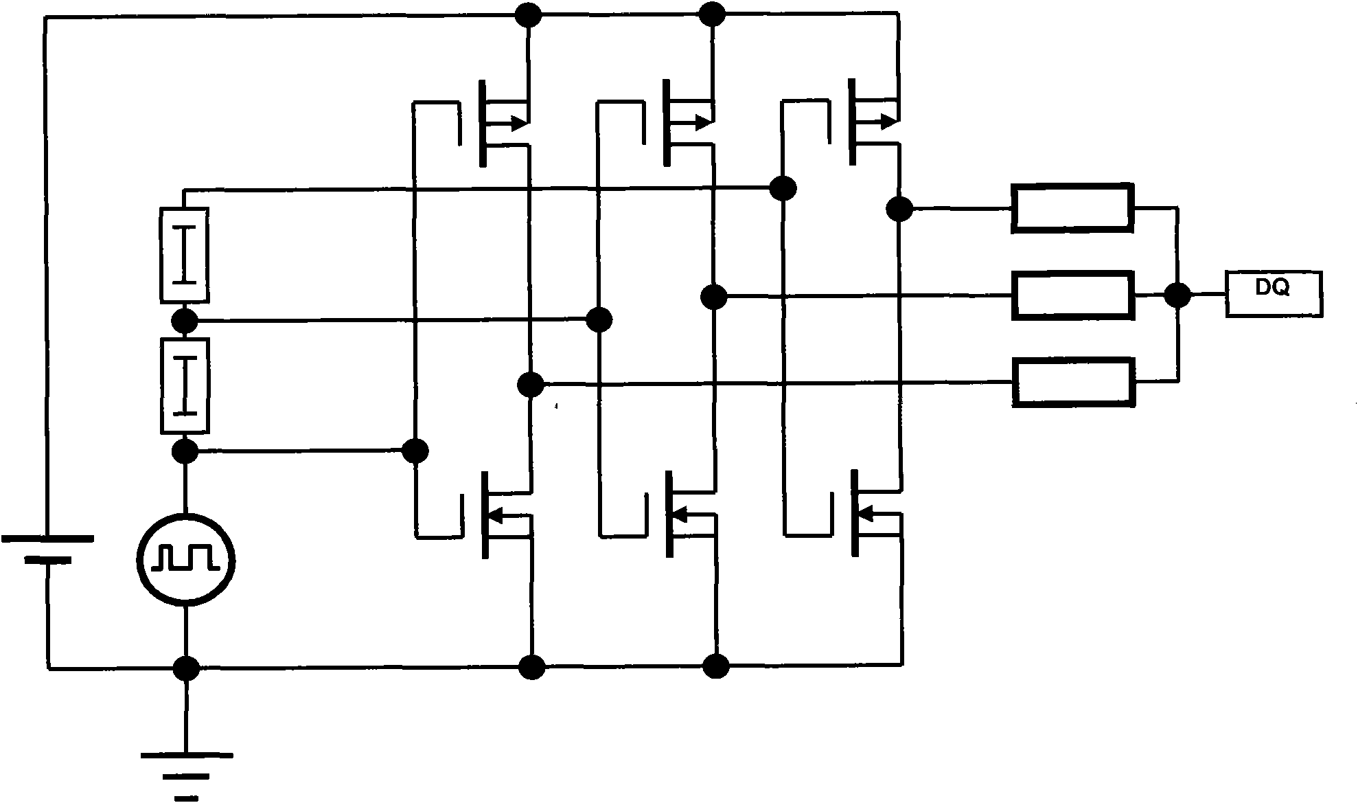
[0005] figure 2 Shown is a multi-domain slew rate control circuit in the traditional technology. This circuit realizes the control of the slew rate through multiple pairs of PMOS transistors and NMOS transistors coupled to each other, but its disadvantage is that it requires more components and will Occupies a large area and does not meet the technical development trend of high circuit integration
[0006] It can be seen that due to the above problems in the traditional technology, it is not only necessary to avoid the influence of process, input voltage and temperature on the slew rate in the design of flash memory input and output, but also not to make the circuit too complicated to increase the area.

Method used


Image

  • Slew rate control device and method
  • Slew rate control device and method
  • Slew rate control device and method

Examples


Embodiment Construction

[0042] In order to make the above objects, features and advantages of the present invention more comprehensible, specific implementations of the present invention will be described in detail below in conjunction with the accompanying drawings.

[0043] In the following description, many specific details are set forth in order to fully understand the present invention, but the present invention can also be implemented in other ways than those described here, so the present invention is not limited by the specific embodiments disclosed below.

[0044] Secondly, the present invention is described in detail in conjunction with schematic diagrams. When describing the embodiments of the present invention in detail, for the convenience of explanation, the sectional view showing the structure of the device will not be partially enlarged according to the general scale, and the schematic diagram is only an example, and it should not be limited here. The protection scope of the present in...


PUM


Abstract

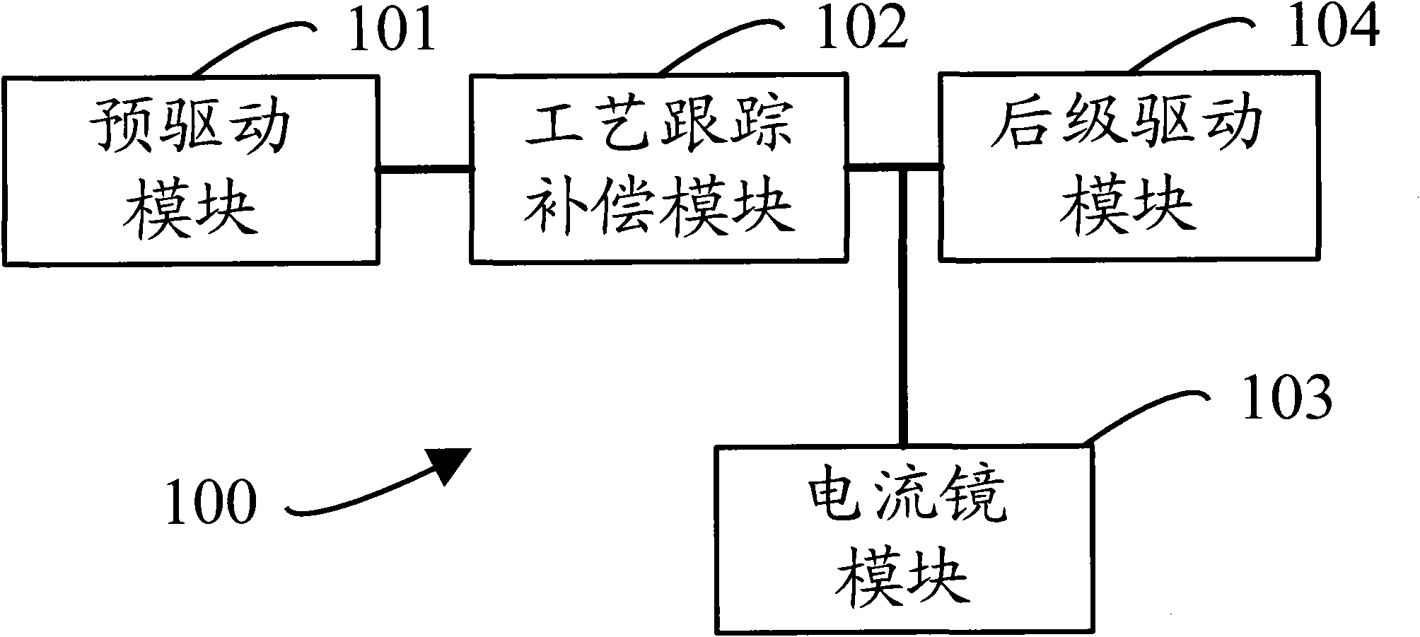
The invention provides a slew rate control device and method. The slew rate control device comprises a pre-driving module, a process tracking and compensating module, a current mirror module and a post-driving module, wherein the pre-driving module is used for applying a pre-driving voltage on the process tracking and compensating module, the process tracking and compensating module is used for compensating the slew rate according to the process condition of the post-driving module under the control of the pre-driving voltage, the current mirror module is used for keeping the rates of charging and discharging the post-driving module, and the post-driving module is used for generating an output voltage and feeding the output voltage to the pre-driving module to generate the pre-driving voltage. By utilizing the slew rate control device and method provided by the invention, the slew rate can be controlled better, and the influence of the input voltage and temperature on the slew rate can be avoided without the increasing of the circuit area.

Description

technical field [0001] The invention relates to the technical field of semiconductor storage, in particular to a slew rate control device and a control method thereof. Background technique [0002] With the widespread application of portable electronic devices such as mobile phones, palmtop computers, and GPS, flash memory (Flash Memory) technology develops rapidly. The main feature of this new type of semiconductor memory is the long-term retention of stored information without power on. In essence, Flash Memory belongs to the EEPROM (Electrically Erasable Programmable Read-Only Memory) type. It not only has the characteristics of ROM, but also has high access speed, and is easy to erase and rewrite, and consumes very little power. [0003] The slew rate (slew rate, SR) is also called the slew rate, which indicates the adaptability of the op amp to the speed of the signal change. The slew rate is an important parameter to be considered in the design of the input and outp...

Claims


Application Information

Patent Timeline
IPC IPC(8): G11C16/06G11C7/10H03K19/003
Inventor 杨光军
Owner SHANGHAI HUAHONG GRACE SEMICON MFG CORP
Learn More