
Decorated panel and connecting structure thereof

A technology for connecting structures and decorative panels, applied in the field of building decoration materials, can solve the problems of difficulty in rapid heat transfer, complex manufacturing processes, long heat conduction paths, etc., and achieve the effects of short heat conduction paths, good thermal stability, and high heat conduction efficiency.

Inactive Publication Date: 2011-04-27
上海阑艺装饰工程有限公司
View PDF6 Cites 7 Cited by
  • Summary
  • Abstract
  • Description
  • Claims
  • Application Information

AI Technical Summary

Problems solved by technology

[0009] Another object of the present invention is to provide a heating cable and the floor into one, which makes it more flexible and convenient to replace the floor or heating elements due to damage during use, and at the same time provides a short heat conduction path. , high heat conduction efficiency, heat can be quickly transferred to a decorative panel on the surface, which solves the problems of the existing technology such as long heat conduction path, low heat conduction efficiency, difficulty in quickly transferring heat to the floor surface, and complicated manufacturing process

Method used


Image

  • Decorated panel and connecting structure thereof
  • Decorated panel and connecting structure thereof
  • Decorated panel and connecting structure thereof

Examples


Embodiment 1

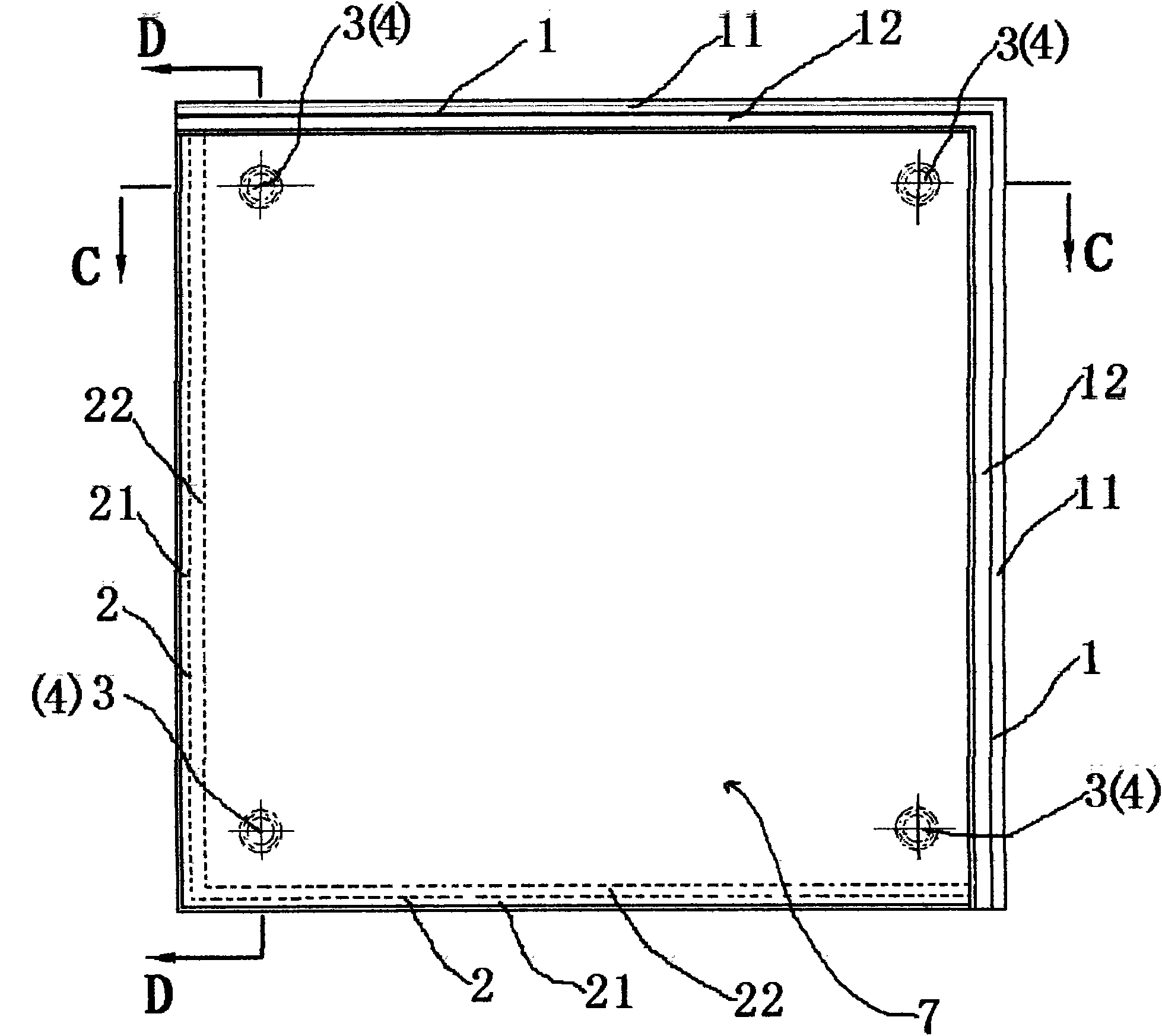
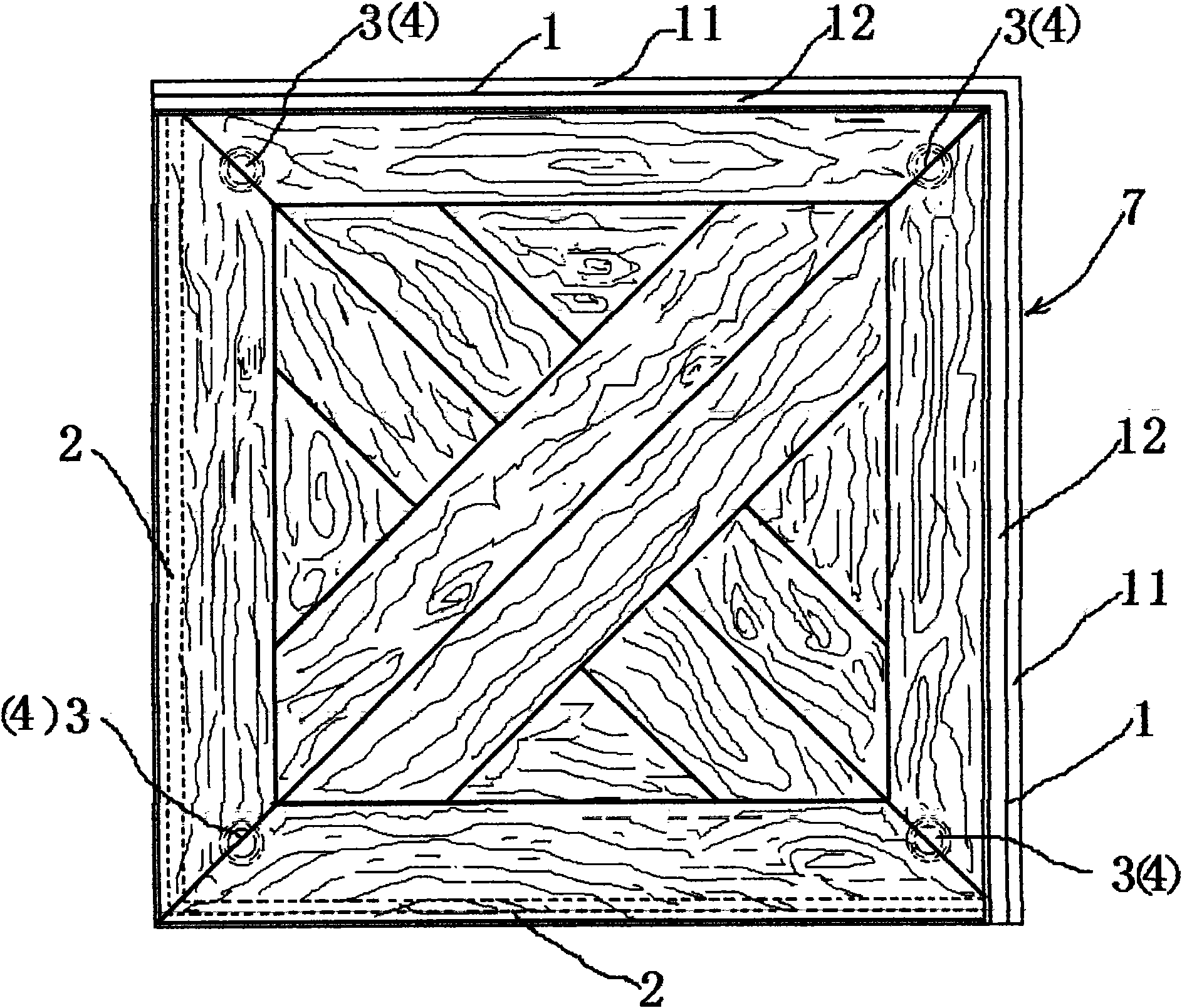
[0033] Embodiment 1: as figure 1 , figure 2 , image 3 , Figure 4 or Figure 5 As shown, a veneer (7) includes a veneer (7) body, the veneer (7) body has an overall square plate-like structure, and the veneer (7) consists of four sides connected end to end, wherein two adjacent A first tongue-and-groove structure (1) extending from the lower bottom of the veneer (7) is arranged on the same side, and the length of the first tenon-groove structure (1) is equal to the lower edge of the veneer (7). The tongue-and-groove structure (1) includes a first tenon body (11) and a first groove body (12), and the other two adjacent sides are also provided with a second tenon extending from the upper surface of the veneer (7) Groove structure (2), the length of the second mortise and groove structure (2) is equal to the upper edge of the veneer (7), and the second mortise and groove structure (2) includes a second tenon body (21) and a second groove body ( 22), the first tenon body (1...

Embodiment 2

[0034] Embodiment 2: as Image 6 , Figure 7 , Figure 8 , Figure 9 or Figure 10 As shown, a connection structure of veneer panels (7), including adjacent first veneer panels (71), second veneer panels (72), third veneer panels (73), fourth veneer panels (74) and common The independent coupling elements (8) connecting them are designed so that the adjacent veneer panels (7) are connected not only by the first tongue-and-groove structure (1) and the second tongue-and-groove structure (2) engaging with each other to form a snap connection but also The common coupling connection of the adjacent first veneer (71), second veneer (72), third veneer (73) and fourth veneer (74) is realized by independent coupling elements (8), wherein the first The first tongue-and-groove structure (1) in the first decorative panel (71) and the second tongue-and-groove structure (2) in the second decorative panel (72) are engaged with each other to form a snap connection. The second tongue and ...


PUM


Abstract

The invention relates to a decorated panel and a connecting structure thereof, which belong to the technical field of building decoration materials. The invention provides the decorated panel with engaged edges, in particular a parquet floor which is made of the decorated panel and has a square surface, and in particular a parquet geothermal floor which is internally provided with a heat-conducting medium and a heating body, and the connection of adjacent decorated panels is not only designed into the locking connection formed through the mutual engagement of tongue and groove structures, but also simultaneously designed into the jointly coupling connection of the adjacent decorated panels realized through independent coupling elements. The invention has the characteristics that the decorated panel is convenient to install, and the all-round locking between the adjacent decorated panels is realized.

Description

technical field [0001] The invention relates to a veneer and a veneer connection structure, belonging to the technical field of building decoration materials. Background technique [0002] In the prior art, such veneers can be arranged in various ways. [0003] The first possibility is that the veneer panels (or floorboards) are attached to the supporting floor, glued together, or nailed together. The disadvantage of this technique is that it is rather complicated and that the sequence change is only possible by damaging the veneer. [0004] The second possible way is that the veneer (or floor board) is loosely installed on the ground, and the veneer (or floor board) is combined with each other by using the connection part composed of tongue and groove, usually with Adhesive is used at the location of the tongues and grooves to hold them together. The veneer (or floor board) obtained in this way has the advantage of being easy to install, and the entire veneer surface can...

Claims


Application Information

Patent Timeline
IPC IPC(8): E04F15/02E04F13/076E04F13/074E04F13/21E04F13/22E04F15/18
Inventor 李增清李渊
Owner 上海阑艺装饰工程有限公司
Learn More