
Swivel table driving device with double worm and gear backlash mechanisms

A technology of rotary table and double worm gears, which is used in hoisting devices, components with teeth, portable lifting devices, etc. The high price of the motor can achieve the effect of high rotary positioning accuracy and repeat positioning accuracy, eliminating the backlash of the reverse drive, and low manufacturing and operating costs.

Inactive Publication Date: 2011-04-27
DALIAN HUAGEN MACHINERY
View PDF5 Cites 17 Cited by
  • Summary
  • Abstract
  • Description
  • Claims
  • Application Information

AI Technical Summary

Problems solved by technology

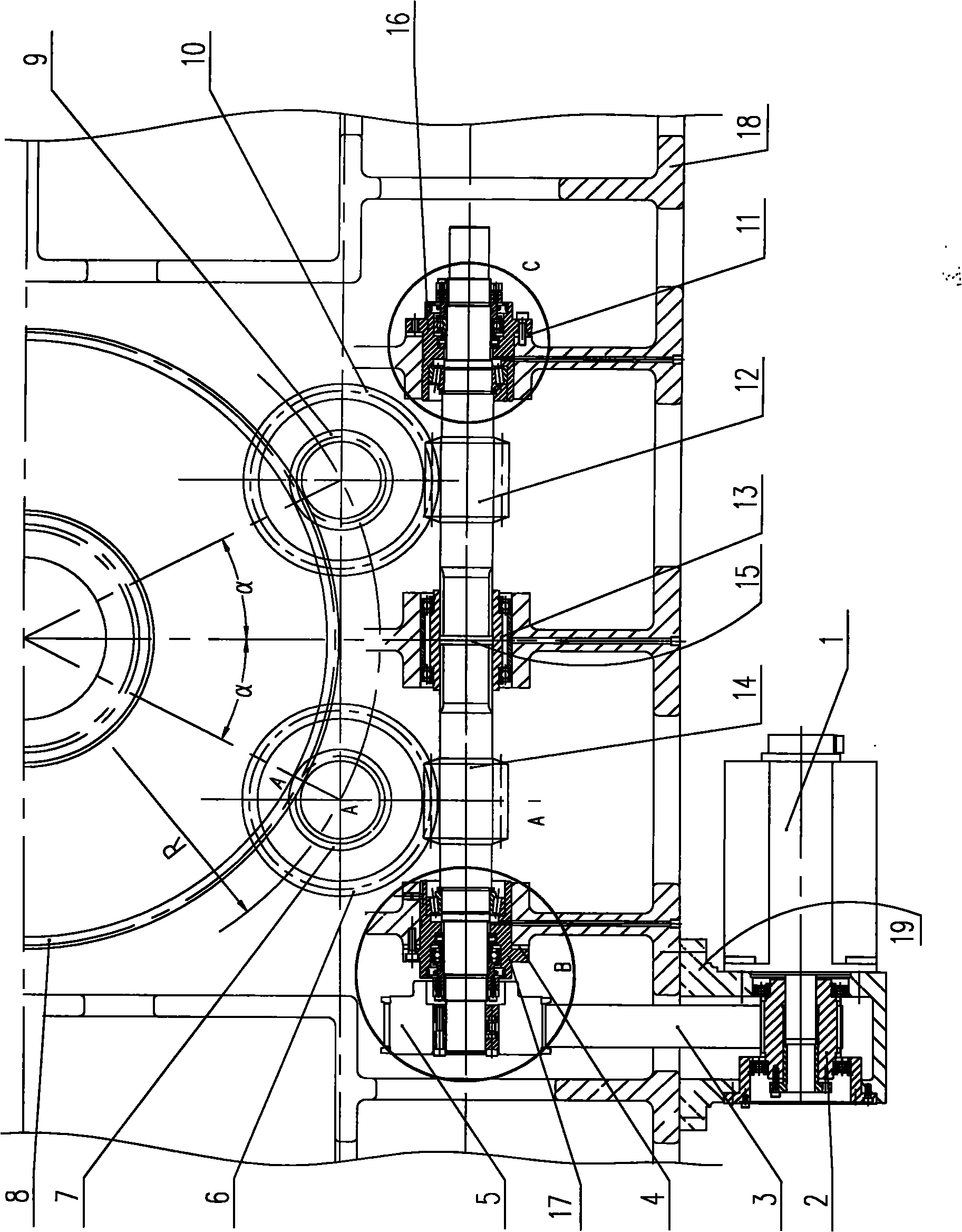
[0003] At present, the rotary motion of the rotary table of horizontal machining centers at home and abroad is realized by two-stage deceleration of worm gear transmission plus gear transmission or three-stage deceleration of belt drive, worm gear transmission and gear transmission. These two transmission methods have inconsistencies. The avoided reverse transmission gap directly affects the rotary positioning accuracy and repeat positioning accuracy of the rotary table, thus affecting the machining accuracy of the machine tool
[0004] In order to avoid the transmission gap caused by the worm gear and gear transmission, some use the torque motor direct drive technology to realize the rotary indexing of the turntable, because there is no intermediate transmission link, and combined with the application of the circular grating, the positioning accuracy and repeat positioning accuracy of this driving device High, but the price of the torque motor itself is relatively high, and the power required for direct drive is higher than that of ordinary servo motors. Using this mechanism will directly increase the manufacturing cost and operating cost of the machine tool

Method used


Image

  • Swivel table driving device with double worm and gear backlash mechanisms
  • Swivel table driving device with double worm and gear backlash mechanisms
  • Swivel table driving device with double worm and gear backlash mechanisms

Examples


Embodiment Construction

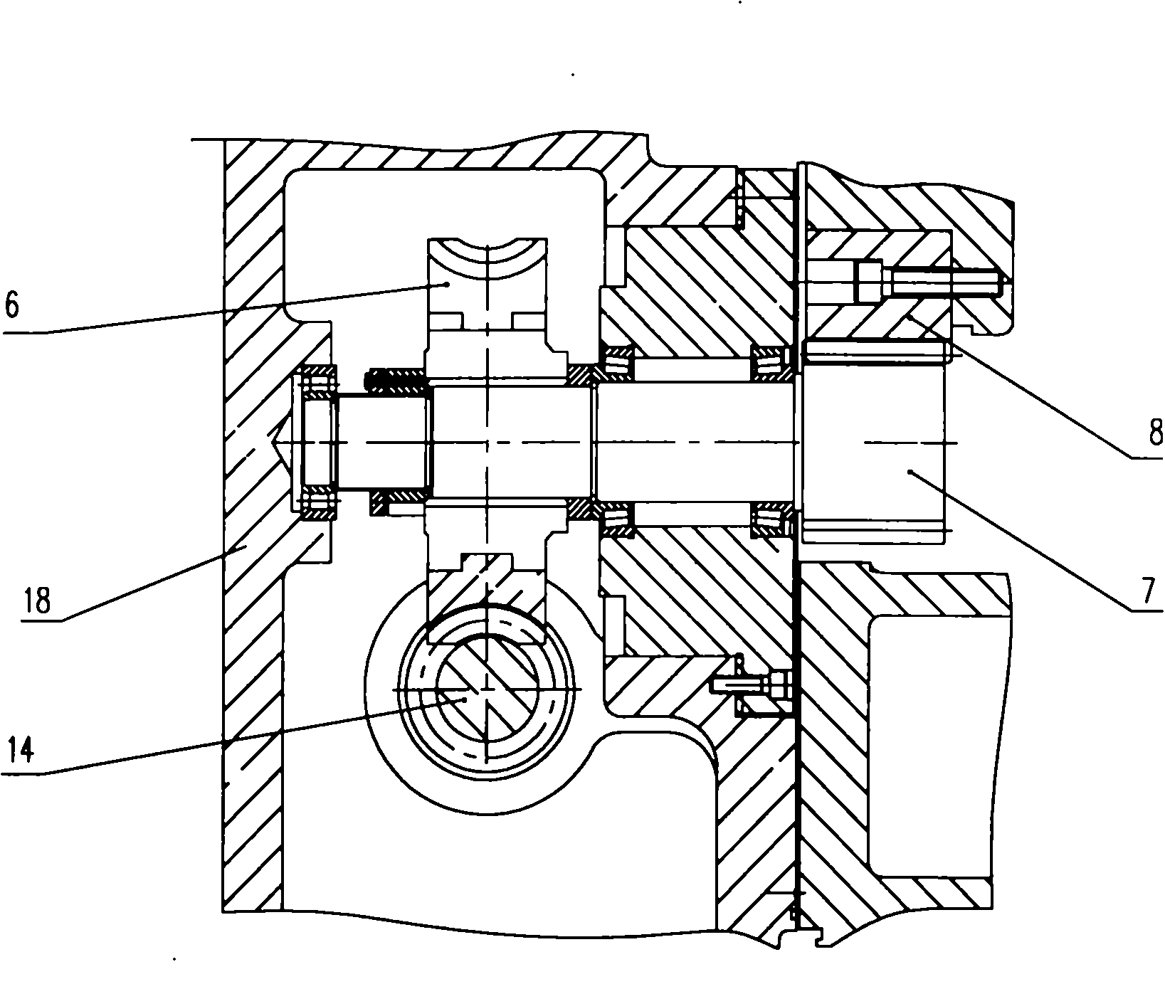
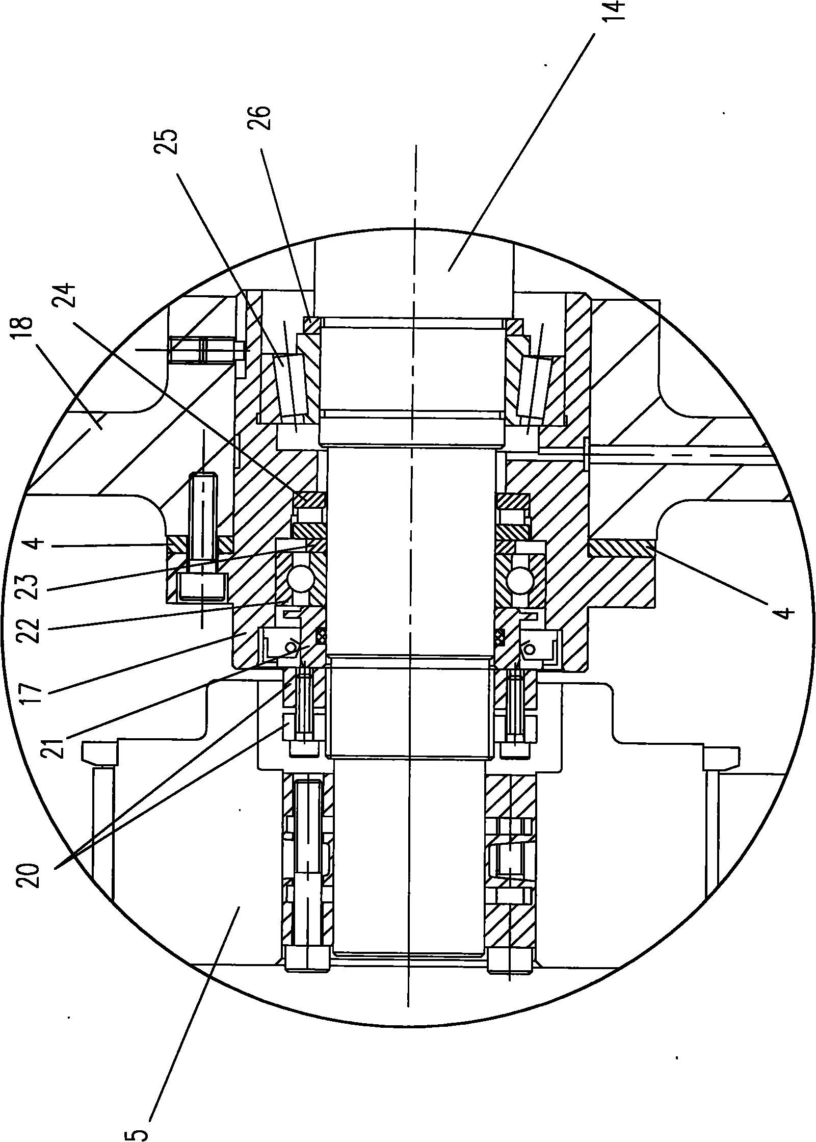
[0012] Such as figure 1 , 2 , 3 shows: 18 is the box body, 8 is the gear ring connected with the rotary table.

[0013] Two sets of worm gear transmission mechanisms are provided on the box body 18, the specific structure is as follows: the box body 18 is supported by a left worm 14 through a bearing, and the left worm wheel 6 and the left gear 7 matched with the left worm 14 are coaxially arranged and supported by bearings. On the case 18, the left gear 7 meshes with the ring gear 8. When the left worm 14 rotates, the left worm wheel 6 and the left gear 7 can drive the ring gear 8 to rotate. The left end of the left worm is fixedly installed with a large pulley 5; a motor seat 19 is bolted to the box body 18, and the motor 1 is fixedly connected with the motor seat 19 by bolts. The output shaft of the motor 1 is fixedly installed with a small pulley 2, synchronous The belt 3 is wound on the small pulley 2 and the large pulley 5 to form a transmission mechanism.

[0014] Such as ...


PUM


Abstract

The invention relates to a swivel table driving device with double worm and gear backlash mechanisms, which comprises a box body and a gear ring which is connected with the swivel table, wherein the box body is provided with two worm and gear transmission mechanisms; the transmission mechanisms are connected between a gear and a motor; a worm is connected with gearwheels coaxial with the worm; the gearwheels are meshed with the gear ring; the axial worm centerlines in both worm and gear transmission mechanisms are in the same straight line; gaps are reserved between adjacent ends of two gears; outer sides of the two ends are sleeved with middle sheaths which can axially move relatively to the gears; and a regulating pad for regulating the axial position of the worms is arranged between a bearing seat for supporting the gears and the box body. The swivel table driving device ensures that the gear ring eliminates a reversal transmission gap during forward-reverse conversion, and has smooth transition. The swivel table has high swivel positioning precision, high repeated positioning precision, low manufacturing cost and low operation cost.

Description

Technical field [0001] The invention relates to a driving device, in particular to a rotary table driving device with a double worm gear anti-backlash mechanism for a horizontal machining center. Background technique [0002] The rotary table is the key functional component of the horizontal machining center. While realizing the linear motion of the machine tool, it provides the fourth linkage axis for the horizontal machining center to complete the rotary indexing and continuous rotary processing, and realize the interpolation processing of complex curved surfaces. Motion positioning accuracy and repeat positioning accuracy are important indicators to measure the technical level of horizontal machining centers. [0003] At present, the rotary table of the horizontal machining center at home and abroad realizes the rotary motion by worm gear transmission and gear transmission two-stage speed reduction or belt transmission, worm gear transmission and gear transmission three-stage sp...

Claims


Application Information

Patent Timeline
IPC IPC(8): B23Q1/26F16H55/24
Inventor 姜美娜刘德栋鞠修勇李全普肖向军高永强马骋
Owner DALIAN HUAGEN MACHINERY
Learn More