
Mechanical step speed changer for harvester

A technology for harvesters and transmissions, applied in harvesters, mechanical drive clutches, mechanical equipment, etc., can solve the problems of heavy transmission weight, time-consuming and complicated operation, and high cost of use, reducing fuel consumption, easy operation, and cost reduction. Effect

Inactive Publication Date: 2011-04-27
TAIZHOU CHANGFA AGRI EQUIP
View PDF0 Cites 7 Cited by
  • Summary
  • Abstract
  • Description
  • Claims
  • Application Information

AI Technical Summary

Problems solved by technology

[0003] At the beginning of the 21st century, domestic harvesters adopted a step-variable walking system with industrial and agricultural gearboxes as the main body. This kind of gearbox is heavy and bulky. Four handles are used to change gears frequently to adjust the forward and backward of the harvester. Changing gears quickly and slowly and turning left and right, the operation is time-consuming and complicated
[0004] However, there is an Achilles heel in the above-mentioned hydraulic continuously variable transmission system, that is, its total efficiency η is on the low side, and the value of η is usually about 52%. The power must be 20kw, of which 9.5kw input power does useless work, wastes energy, increases emissions, and at the same time because of its large fuel consumption, the use cost is high

Method used


Image

  • Mechanical step speed changer for harvester
  • Mechanical step speed changer for harvester
  • Mechanical step speed changer for harvester

Examples


Embodiment Construction

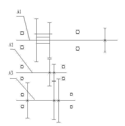
[0028] Such as figure 1 As shown, the transmission system of the present invention includes a power input shaft system A1, an intermediate shaft system A2, and a power output shaft system A3 arranged in parallel in sequence.

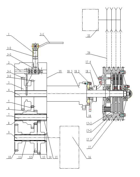
[0029] Such as figure 1 and figure 2 As shown, the power input shaft system includes a double sliding gear 3 installed on the power input shaft 4, and a clutch assembly 17 and a separation pawl system assembly 18 installed on the input end of the power input shaft 4; :Double sliding gear 3 includes parallel sliding gear Ⅰ3-1, double sliding gear Ⅱ 3-2; clutch assembly 17 includes clutch 17-1, friction plate 17-2, light plate 17-3 and clutch Lever 17-4; the separation claw system assembly 18 includes a separation claw 18-1, a separation claw seat 18-2, and a separation coupling sleeve 18-3.

[0030] Such as figure 1 and figure 2 As shown, the intermediate shaft system includes a sleeve I8, an intermediate large gear 5, an intermediate pinion 6, and a shaft...


PUM


Abstract

The invention provides a mechanical step speed changer special for a harvester, which is low in oil consumption and simple and convenient for operation. The mechanical step speed changer comprises a manipulating unit and a gear speed change unit. The manipulating unit and the gear speed change unit are connected. The gear speed change unit comprises a power input shaft system, a middle shaft system and a power output shaft system arranged in parallel in sequence. The power input shaft system comprises a power input shaft and a speed-change combined gear assembled on the power input shaft. A power separator for cutting the power input during gear shaft operation is assembled at the input end of the power input shaft. The manipulating unit can drive the speed-change combined gear to axially slide along the power input shaft to realize engagement of corresponding gears among shaft systems. The middle shaft system comprises a middle shaft and a middle rack wheel and a middle pinion which are assembled on the middle shaft. The power output shaft system comprises a power output shaft and a high speed output gear, a back output gear and a low speed output gear which are assembled on the power output shaft. The back output gear on the power output shaft is always engaged with the middle pinion on the middle shaft.

Description

Technical field [0001] The invention relates to a speed change mechanism, in particular to a mechanical stepped transmission installed on a harvester. Background technique [0002] In the current domestic harvester market, there are two types of walking systems for crawler rice-wheat combine harvesters: one is equipped with industrial and agricultural gearboxes, which belong to mechanical stepped transmission; the other is to install a FYW28 on the NL35 gearbox. Hydraulic continuously variable transmission. [0003] At the beginning of the 21st century, domestic harvesters adopted a step-variable walking system with industrial and agricultural gearboxes as the main body. This kind of gearbox is heavy and bulky. It needs four handles and frequently changes gears to adjust the forward and backward movement of the harvester. Fast and slow gear changes and left and right steering, the operation is time-consuming and complicated. Therefore, more users favor the hydraulic continuously ...

Claims


Application Information

Patent Timeline
IPC IPC(8): A01D69/06F16H3/091F16H55/17F16H57/02F16H63/32F16D13/40
Inventor 孙慕利曹扬崔威风常巧云王阿祥薜臻叶晶
Owner TAIZHOU CHANGFA AGRI EQUIP
Learn More